Creating Logical Connections | ||||||
|
| |||||
- From the Edition section of the action bar, click Create Logical Connection
 .
Note: The command is also available in the context menu.
.
Note: The command is also available in the context menu. - Click OK.
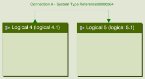
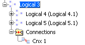
The two logical components are connected.
The logical connection is displayed in the tree and the 2D graph.
Warning: When connecting two logical components from different level in the structure, a port is created for all impacted component. In this example, the connection impacts three components: this connection creates 3 ports and 2 connections.
 Notes:
- The broadcast is possible on output ports: several connections can start from the same output port.
- The connected ports must have the same type (or both not typed). If you select a port with type and a port without type, the command automatically assigned to the port without type the type of the other port.
- The concentration of several connections on one input (or In/Out) port is not supported. In the case of a No Direction port, the concentration is possible (A=B=C).
- The selection of an input port already connected to a logical connection is not supported when creating a logical connection (except if it is a port of direction No Direction).