About Panels and Plates | |||||
|
| ||||
Support
For creating panels or plates, you need to select a support. You can select multiple supports. You can:
- Select a reference plane or a surface from the work area.
- Select the reference plane by clicking
 in Support Toolbox.
 - Create a plane or a surface to define the support using other commands in Support Toolbox.
- Select a structural object (panel, plate, or profile) from the work area. The supporting reference plane for the structural object is selected as the support.
To modify the selected support, click the  button to display the elements list. Click
  to remove the selected support. To replace the selected support, click
  and select another support from the work area.
Limits
You can select:
- Geometrical entities
- Structural objects (panels, plates, and profiles)
- A volume or a closed surface.Note: When the limiting object has poor quality, sharp curvature, or complex geometry, the panel or plate is created with simple thick surface from the Delimited Molded Surface (DMS) of the panel or plate.
- Particular faces of the stiffener as the limiting elements. Press the Alt key while selecting the stiffener. It displays the faces which can be selected as a limit. Note: If an opening interrupts the stiffener, the complete stiffener is used as limit.
You can select reference planes in the work area or by clicking in the Limit Toolbox. You can also create plane or line.

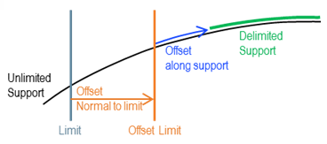
You can define the required offsets to the limits.
- Normal Offset: Defines the offset normal to the
limit.
You can apply the normal offset only if the limit is a planar surface.
- Offset: Defines the offset along the support.
If you specify both offsets, the normal offset is applied first followed by the offset along the support. The orientation of the normal offset differs from the offset along the support. The normal offset follows the global orientation.
You can define the limit details by selecting any of the following options:
| Coarse | Intermediate | Fine |
|---|---|---|
| Ignores the split plates. When a panel is selected as a limit, only the thickness of the panel is taken into consideration. Select this option for early designs when modifications are frequent. | Considers thicknesses of all the plates. When a panel is selected as a limit, the thicknesses of its split plates are considered and the thickness of the closest plate is selected. Select this option when difference in the thickness of the split plates is small. | Considers the detailed geometry of the panel. The delimitation is performed
with respect to the exact geometry of the limit. Select this option when you
prefer geometry precision over performance. The delimitation fails if the geometry of the limiting panel is interrupted by an opening. |
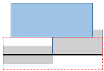 | 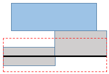 | 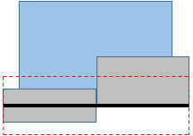 |
| Notation | Description |
|---|---|
 | Delimited Molded Surface (DMS) of the limiting panel |
 | Plates of the limiting panel |
 | Thickness of the limiting panel |
 | An object to be limited |
Material and Thickness
- Preferred values only
- Shows only recommended combinations of material-grade and thickness. If the material table is not set in the Data Setup, this option is unavailable.
- Material
- Lists the materials. The material is pre-selected based on the previous session.
- Thickness
- Lists the thickness value. The thickness is pre-selected based on the previous session.
- Thickness Offset
- Specify the required thickness options:
- Center: applies thickness equally on both sides of the support.
- Offset: applies thickness at the defined offset value. Specify the offset value in the box.