Manage Attributes on the Fastener Reference
-
Locate the Fastening
app
standard file (Fst_Standard.xls).
-
Edit the standard file as follows:
-
Add the "Structure" category in the "FTYP_CLASSATTRCATEGORIES" row.
-
Insert a new row, "FTYP_CLASSATTRLIST_Structure", and define attributes in it,
for example, the "Joint" attribute.
-
Edit the excel file of the required process type, MIG, for
example.
-
Add the attributes in the "Fst_CLASSATTRLIST" row.
-
Insert new rows for specifying the values of the attributes. For example, insert
a "Fst_CLASSATTR_Joint" row for the "Joint" attribute and specify its value.
For more information about customizing the fastener standard files, see
Fastening User's Guide: Administration: Working with the Fastener Standard and
Reference Fastener Type Files.
Create a Fastener Reference
-
Create a unified bead fastener reference.
-
Select
-
In the New Content panel, expand
Fasteners and select Unified Bead
Fastener
 . .
-
Create a physical product with a 3D shape and switch to the Fastening
app.
-
Instantiate the unified bead fastener reference under the physical product with the
Explicit Mode
 location
option, using the Fastener Instantiation location
option, using the Fastener Instantiation
 command. For more
information, see Fastening User's Guide: Instantiating Fasteners: Instantiating Bead Fasteners and Unified
Bead Fasteners. command. For more
information, see Fastening User's Guide: Instantiating Fasteners: Instantiating Bead Fasteners and Unified
Bead Fasteners.
-
Right-click the unified bead fastener's node in the tree, select Properties, and click Reset instance
position to identity
 in
the Position tab. in
the Position tab.
Create the Fastener Geometry
-
In the fastener reference, create a parameter and name it 'Reference'.
This parameter is used to recognize the original fastener reference. During
generation of the fastener, the value of this parameter is assigned automatically from
the value of the "ResourceIdentifier" keyword in a catalog or classification attribute
in a library.
-
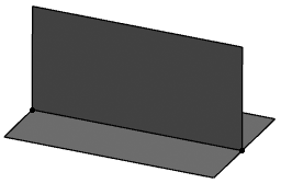
Under a geometrical set, create two surfaces as shown below to represent a dummy
pilot and joined part geometry.
-
Define input geometry.
Create input features. The input features are replaced with the computed geometries
of the pilot and joined parts. There are two methods to replace the input
features:
- Replace the input features with the automatically computed geometry.
- Replace the input features with the named geometry, using key names.
Notes:
- The input features must be aggregated under a geometrical set named
"Input".
- The features must be of the multiple extract type.
- Input features must respect the following naming convention: (Object
Type)_Input_(Numbering)_(Geometry Type)_(Usage)
- Object Type: Plate or Profile
- Geometry Type: Face, Edge, ResultFace, or ResultEdge
- Usage:
-
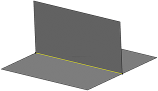
Define a result geometry for the fastener curve.
- For the computed geometry, create an interference feature between the input
features.
- For the named geometry, define a curve as required from the input features.
-
Edit the unified bead fastener reference and change the location option to
On Curve Mode
 and select the
curve. and select the
curve.
-
Edit the engineering connection of the fastener.
-
Remove the RollCurve type constraints
-
Set the constraints type to User Defined.
-
Isolate the unified bead reference from the product using the Links and
Relations command.
|
 > Preferences > App Preferences > 3D Modeling > Multi Discipline Engineering
to find the location of the standard file.
> Preferences > App Preferences > 3D Modeling > Multi Discipline Engineering
to find the location of the standard file.

