About Members | ||
| ||
Members are used for providing support to the structure objects (panels, plates, or another beam). A member can carry the force in longitudinal or lateral direction.
- To edit a previously created member, select the
member in the
work area
and click
Member
 on the
context toolbar.
on the
context toolbar.
- If the member location is changed, the end cut location is also updated.
- During multi-creation and multi-edition of members, the handles are shown only for one member.
- During creation or edition, if you delete the
following main inputs of the member, the member gets deleted.
- Member - Point Length: Point
- Member - Point Limit: Point
- Member - Point to Point: Start and end points
- Member - Curve: Curve
- Member - Reference Supports: Any of the reference supports
Orientation
You can get the required orientation of the member using the following tools:

|
Show Anchor Point |

|
Hide Anchor Point |

|
Flip Flange Orientation |
| - | Angle handle |
While creating a member, its web orientation is decided as follows:
- If the member's unlimited trace is parallel to z direction, the web orientation will be along +y direction.
- If the member's unlimited trace is not parallel to z direction, the web orientation will be along the +z direction.
Limits
In the Limits area, you can apply the required start and end limits, normal offset, and offset along the support. You can also set the required limit type for each limit. Depending on the beam type selection, you can select reference planes, panels, plates, points, surfaces, or another profile as limits.
- When you select a profile as a limiting element, depending on
whether the traces of the profiles intersect, the system automatically selects
the delimited trace, flange, or web as a limiting element. You can specify when
the system must select a web face as a limit. To manage the angle at which a
web should be selected as a limit, select
Me
 > Preferences > App Preferences > 3D Modeling > Multi Discipline Engineering
> Structure Design >
General. For more information, see
Profile sub-element selection.
> Preferences > App Preferences > 3D Modeling > Multi Discipline Engineering
> Structure Design >
General. For more information, see
Profile sub-element selection.
- If the section, category, or other parameters of the limiting profile changes, you need to manually update the limits. For this, right-click the beam and select Member.x object > Update Limits.
- You can also select manually a particular face of a profile as limit by pressing the Alt key.
- The system requires the key on the profile face to identify and select the limiting sub-element. If the profile face does not have the assigned key, the system fails to select it. For more information, see Naming Section Edges.
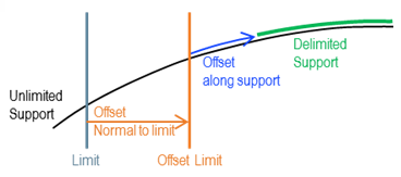
- You can extend the profile beyond its original trace by either setting the limiting objects or applying offsets to the limits. You can extend each extremity up to 30% of the length of the original trace.
You can define the required offsets to the limits.
- Normal Offset: Defines the offset normal to the
limit.
You can apply the normal offset only if the limit is a planar surface.
- Offset: Defines the offset along the support.
If you specify both offsets, the normal offset is applied first followed by the offset along the support. The orientation of the normal offset differs from the offset along the support. The normal offset follows the global orientation.
You can select the required Limit Type from the list:
| Limit Type | Description | Illustration |
|---|---|---|
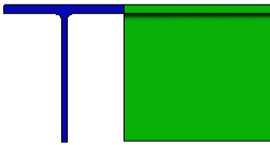
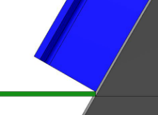
| Short Point | The profile remains in contact with the limiting element at the short point. |
 |
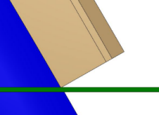
| Long Point | The profile remains in contact with the limiting element at the long point. |
 |
| Weld | The profile remains in contact with the limiting element completely. |
 |
| Metal To Metal | The profile remains in contact with the limiting element at any point of its extremity. |
 |
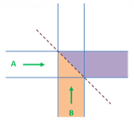
| Miter | A miter cut is a mutual limitation between two
profiles.
For example: Two stiffeners, A and B, are limited with each other. For A limited with B, B stiffener limits A at the start extremity and A limits B at the end extremity. |
 |
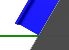
| Web Weld | The profile is cut by a plane which is perpendicular to the profile's web and keeps the profile close to the limit. |
 |
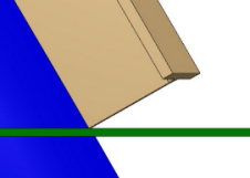
| Flange Weld | The profile is cut by a plane which is perpendicular to the profile's flange and keeps the profile close to the limit. |
|
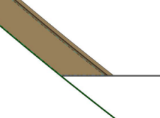
| Limit Trace | The profile is cut by a plane which is perpendicular to the profile's trace and ensures that the profile and the limiting element are in contact at the section's anchor point. |
|
| Up to Limit | The profile is extended until the last contact point between the limiting and limited profiles. No material is removed from the clash. | 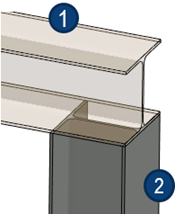
|
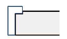
| Short Weld |
The Weld limit type takes into account the first contact point between the limited profile and the web of the limiting profile. Whereas, the Short Weld limit type takes into account the first contact point between the limited profile and the limiting profile. You can use this type to avoid a clash with the flange of the limiting profile. Note:
Use this limit type only when the limiting element is a
profile.
|
 |
 : Limited profile
 : Limiting profile
- While creating a profile, you can select the required limit type from the context toolbar. The context toolbar appears when you pause the pointer over the profile extremity.
- When you click Miter in the context toolbar, two arrows appear to select the side to keep. Click the required arrow to remove the profile material on the other side.
- You must use the Metal To Metal, Miter, and Short Weld limit types only when the limiting element is a profile.
- Click Swap Ends to toggle between Start and End.
- If you click Miter again for the existing Miter limit type, the orientation of the limiting profile is inverted.
- When modifying the profile limit, you can use commands in the context toolbar to delete or change the applied limit type.
- Although Weld and Short Weld provide a complete contact with the limiting object, there might be some gap or clash depending on the complexity of the limiting object.