Integrating Logical Data with Physical Data

You can integrate the logical data with the physical data using the Logical to Physical command.


Before you begin:
  • Create a piping/tubing/HVAC logical system containing equipment, pipe/tube/duct, piping/tubing/HVAC valve. For more information, see Piping & Tubing Systems Design User's Guide.
  • Create the physical structure containing equipment.
  • Create implement links between the logical and physical components. For more information, see Functional & Logical Design User's Guide: Creating Implement Relations.
  • Create the pathway in the piping/tubing/HVAC logical system. For more information, see Systems 3D Allocation: Working with Pathways.
  • Assign the predefined part number to the equipment, ports of equipment.
  • Define logical subtype and its equivalent physical subtype in the Mapping Part Subtype file of the Piping/Tubing Discipline Resources in the Data Setup.
  1. Double-click the Physical component node from the RFLP structure tree.
    The app switches to Piping & Tubing 3D Design or HVAC 3D Design.
  2. From the Line IDs section of the action bar, click Logical to Physical.
    The Logical to Physical Synchronization Manager dialog box appears.
  3. Select the logical or physical elements to be synchronized.
    The selected elements are highlighted. In the Selected Elements list, all the selected elements are displayed with their Type (either Logical or Physical).
    Notes:
    • You can deselect the selected element by clicking it once again or right-click the element and select Remove.
    • You can sort the elements by clicking the Selected Elements list or Type list.
  4. Optional: Select Scan and resolve links.
    The Analyze button is replaced by Scan Links.
    1. Select the elements you want to scan.
    2. Click Scan Links. A partial analysis is performed on the selected elements to find the physical elements corresponding to the logical. The list of logical elements is displayed with a status showing if the logical element is linked or not. There are three different statuses:
      • Linked: the logical element is linked to a physical element through an implement link
      • Linked by Business rule: the logical element is linked to a physical element through a business rule
      • Unlinked: the logical element has no implement link with a physical element.
    3. Select a logical element with the unlinked status. A list of compatible elements is displayed on the right.
    4. Select one of the compatible elements. The logical element is now linked to a physical element and its status changes to Linked by user.
  5. Click Analyze.
    The selected elements are analyzed. An analysis progress bar helps to view the analyzing status of elements and connections.

    For more information, see More About Logical to Physical Integration.

    You can generate an analysis report in the form of an HTML file in the synchronization report repository by clicking the Generate Report. For more information, see About the HTML Report.

  6. In the Status list, you can determine either to synchronize the element by selecting Accepted or Rejected.
  7. Select a physical reference for a logical route:
    1. Right-click the logical route in the Logical To Physical Synchronization Manager dialog box.
    2. In the context menu, click Select routable attributes.
    3. Select a reference in the Select routable attributes dialog box and click OK.
      Note: The Flexible attribute from the logical route is taken into account to define the type of the physical route: rigid or flexible.
  8. Click Synchronize to synchronize the selected elements.
    The selected elements are synchronized.

    You can generate synchronization report in the form of an HTML file in the synchronization report repository by clicking the Generate Report button. For more information, see About the HTML Report.

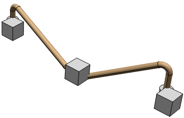
    In the work area, the predefined parts are instantiated from the database.