About Grid Annotation Templates | |||||
|
| ||||
Concepts
Grid annotations can have a ruler line and be translated along its representative planes. If the grid has two sets of representative planes, the grid is fixed.
Grid annotations can be of any shape, with lines and circles as geometry, area fill, texts, and so on. Few examples of grid annotation are as shown below:
 |
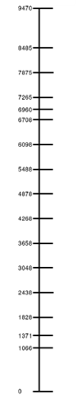 |
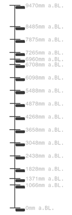
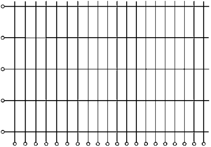 Shipbuilding horizontal and vertical ruler line grids. |
 |
||
Grid Annotation Basics
Annotations such as grid, elevation, spot, etc. use annotation templates. A template is an extended 2D component in a detail sheet. For more information about 2D components, see 3D Modeling: Mechanical Systems: Drafting User's Guide: Working with 2D Components: Creating a 2D Component Reference.
Grid template is an annotation template containing instances of grid line templates as sub-annotation templates. It also maps grid line templates on the 3D plane categories.
It can be instantiated into grid template using Sub-Annotation Template command of Smart Annotation Templates toolbar.
It is an annotation for which sub-annotation template position is not relevant and can be placed anywhere and oriented at any angle within the grid template.
Grid template is designed horizontally.
The grid template can be organized so that grid line templates are placed along ruler line template if any or along X axis.
It can be oriented as per intended direction (angle of 2D component Instance can be modified editing its properties). It also enables to test grid line template behavior in terms of rotation and to check that the expected result is reached in the target orientation, especially concerning text alignment and flip.
Template or Category Mapping
The category of a 3D plane can be as follows:
- If the plane is an Space Reference System (SRS) plane:
- Its category if it is set.
- The name of the set it belongs to if it is not set (for example, RFGGridFace).
- Its name
For a particular category, the grid line template to be used is the one referenced by the instance containing the category in its name.
Therefore, grid line template instances within grid template have to be named according to the following rule:
Component Instance name = <Category1> [ & <Category2> & … & <CategoryN>]
Sample
GridTemplate1
└ Component Instances
├ Category1 & Category2 > GridLineTemplate1
└ Category3 > GridLineTemplate2
GridLineTemplate1 is used for both Category1 and Category2 planes.
GridLineTemplate2 is used for Category3 planes only.
Ruler Line
Drafting Template Design supports ruler line grids. Such grids are made of main lines and an orthogonal line extending up to both extreme main lines.
Ruler line is considered if a single linear plane set is detected from
3D planes and categories supported by the selected template. Additionally, the
RulerLine parameter is to be added under the grid
template.
The following behaviors result from its values:
| Value | Description |
|---|---|
| Free | Ruler line is free to move but does not have any corresponding template: ruler line will not have any representation. |
| Free | Ruler line is free to move and has a corresponding template: ruler line will have a representation given by GridLineTemplate. |
| Category 1 | Ruler line is not free to move: it will be aligned on Category1 planes only. It has a corresponding template so will have a representation given by GridLineTemplate1. |
| Free
Category 1 |
Ruler line is free to move: its representation is given by GridLineTemplate. When aligned on Category1 planes, its representation is given by GridLineTemplate1. |
Extremities
Drafting Template Design manages the grid line with extremities to support civil engineering style grids. To define extremities within grid line template, two sub-annotations have to be created and named as ExtremityLabel and ExtremityNoLabel.
ExtremityLabel: sub-annotation to define template for extremity with label must respect the following constraints:
- Distance along X is the distance from line end point at which extremity is initialized.
- Distance range along X must be set from 0mm to <Sup. Range> mm so that line can be extended. <Sup. Range> being the maximum distance from the middle of the line.
- Flip along X in position and content must be activated so that template can be evaluated for both end points of the line.
- Distance range along Y can be set so that extremity can be moved.
- Related template can contain sub-annotation representing the label itself and some driven line geometry linking the label to the line body.
ExtremityNoLabel: sub-annotation to define template for extremity without label must respect the following constraints:
- Distance along X is the distance from line end point at which extremity is initialized.
- Distance range along X must be set from 0mm to <Sup. Range> mm so that line can be extended. <Sup. Range> being the maximum distance from the middle of the line.
- Flip along X in position must be activated so that template can be evaluated for both end points of the line.
- Distance range along Y can be set so that extremity can be moved but extremity without label can be moved only along the line.
- Related template cannot be empty and must contain at least a point that is not displayed in instantiated grid.
Geometry
The first geometric line in template is published in annotation instance and thus selectable by user.
The main line of grid line template to be the first geometry so that it is selectable for dimensioning or any operation that needs your selection.