Isometric and Assembly Piping Batch Parameters

This section describes the parameters of the Isometric Pipe Spool Drawing batch.

The drawing profiles are defined in an Excel sheet that is linked to the resource set in the Data Setup. One Excel file can define one or more drawing profiles, so that the user can choose different profiles. The Excel file must contain a single sheet that contains drawing profile parameters in the first row. Then rows 2, 3, etc., can contain the drawing profiles with their corresponding values.

This page discusses:

Configuration Parameters

Parameters Description Default Value
ConfigurationName

Name of the drawing profile that you choose.

MDD-Standard-Iso-MM
ISOSheetTemplate

Name of the sheet template from the sheet template chapter.

ASD A3-Sheet-For-ISO-Pipe-Batch-Drawings
BOMTableTemplate

Name of the table template from the table template chapter.

Piping BOM Table Template
ISOStartModelName

Name of the start drawing. This drawing is duplicated when a new drawing is generated. For example, a drawing with an empty A3 sheet.

Example- Iso
ISOStartModelRevision

Start the drawing major revision to be used.

A

Dimension Parameters

Parameters Description Default Value
DimFontName Font name of dimension value. Arial (TrueType)
DimFontSize Font size of dimension value. 2.5
DimValueDistToLine Distance of the dimensions value from the dimension line. 1.5
DimLineSymbol End symbol of the dimension line. 1
DimDimToGeoDist Distance ISO geometry to the first dimension line. 14
DimDimToDimDist Distance between dimension lines 2, 3, 4. 9
DimFormatName Description of the dimension value format. Typical value for imperial is: FEET-INC. NUM.DIMM
DimFormatDisplayFactor Dimension Value Factor

1 for NUMM.DIMM.

Use 2 for FEET-INC

1
DimFormatType Whether dimensions are displayed in decimal format (CATDrwDimFormatDec) or in fraction format (CATDrwDimFormatFrac) as is typical for imperial dimensions. CATDrwDimFormatDec
DimFormatPrecision Number of significant digits for dimension value (or fraction base, for example, 16 for fraction format). 1

ISO Specific Parameters

Parameters Description Default Value

ISOCatalogName

Name of the Catalog that contains ISO symbols. MDD-ISO-CATALOG

ISOSymbolChapterName

Name of the Chapter that contains ISO symbols. ISO-SYMBOLS

ISOXDirection

Orientation of the isometric relative to the plant/ship global axis:
  • 1=+X to lower right
  • 2=+X to upper right
  • 3=+X to upper left
  • 4=+X to lower left
4

ISOsymbsizeonpaper

Size of the ISO symbol on paper (mm) 10

PipeGeoThick

Line thickness for the piping pipe representation. 3

PipeGeoColor

Line color for the piping pipe representation. 0,0,0

PipeSymbThick

Line thickness for the piping pipe representation. 3

PipeSymbColor

Line color for the piping pipe representation. 0,255,0

PipeGeoLineType

Line type for the piping pipe representation. 1: solid line

PipeInsulatedGeoLineType

Line type for the Insulated Piping Part representation.

For insulated pipes, a segment is created with custom line; a double line with the top line having a dashed profile.

Number of custom lines used

BoxToGeoDist

Opening gap at the corners of the box. 4

BoxGeoThick

Box geometry thickness. 1

BoxGeoColor

Box geometry color. 255,0,0

BoxAngleTol

Minimum angular direction change introducing a horizontal direction change (box or triangle). 1

BoxVisuType

Types of visualization:

  • 0 (undefined) - Creates a box when the pipe is bent within two planes.
  • 1 - Creates a triangle.
  • 2 - Removes the triangle and box and creates a slope angle annotation.

0

HatchDist

Distance between hatch ticks (used for single direction change triangle). 3

HatchNumb

Quantity of hatch tick (used for single direction change triangle). 10

SlopeAngleMin

Slope angle larger or equal to this angle is considered slope. 0.5

SlopeAngleMax

Slope angle smaller or equal to this angle is considered slope (so slope annotation, not box, or hatch). 3

SlopeAnnotationVisuType

Changing the angle format switches the slope from “1:x” to x:deg”.

  • 1: angle percent
  • 2: slope fraction
-

ShowSlopeAnnotation

  • 1: Shows slope annotation if the angle is less than 3 degrees.
  • 0: Hides slope annotation. Box/triangle is shown.

Note: ShowSlopeAnnotation can be overridden by changing the BoxVisuType value to 2.

1

DeltaDirection angle

Delta direction angle can be added to an isometric profile to offset the rotation. 0

AnnotationFontSize

Manages the global annotation font size. 2.5

Note:

Isometric drawing annotations can be created with and without the templates.

If templates are not used, the configuration for annotation font size and font name is considered from the drawing profile.

AnnotationFontName

Manages global annotation font type. System default or Arial (TrueType)

AnnotationPlacementNumberOfSteps

Determines the optimized value of maximum steps in the spiral direction for the annotation placement. 400

AnnotationPlacementMaxStepX

Maximum distance of step.

X direction

If the value is bigger than the bounding box of an annotation, the step is equal to the size of the annotation.

400

AnnotationPlacementMaxStepY

Maximum distance of step.

Y direction

200

NoDimmAndBoxOverride

  • 0 or not defined: Creates the dimensions and slope box or triangle.
  • 1: Removes all dimension overrides and no dimension and slope box or triangle is placed.
  • 2: Auto - if the assembly contains loose parts, then for the spools under the assembly dimensions are removed and for the loose parts the dimensions are kept.
0 (valid 1, 2)

LocalAxisSystemStrategy

Manages the axis system selection.
  • 0: Selects the default global axis system.
  • 1: Lets you manually select the local axis system.
0

MinimalRunLenghtOnPaper

Minimum length required of a run on paper when parallel to XYZ. 0 =< for example 25mm

MinimalRolledRunLenghtOnPaper

Minimum run length required of a run on paper when not parallel to XYZ (so when it has a box or triangle). 0 =< for example 35mm

PipeCrossingGap

Distance on paper between a pipe crossing another pipe. 4mm

AttachDrawing

  • 0: Do not attach drawing.
  • 1: Attach drawing under direct father (Pipe or HVAC spool).
  • 2: Attach drawing under assembly.
0

Compass Annotation

Parameters Description Default Value
CompassAnnotationTemplate Path to compass annotation template for automatic placement inside an ISO view. ASD Compass Annotation Catalog\AxisWithArrows
CompassAnnotationPosition Default placement of compass annotation (upper-left, lower-left, left, upper-left, lower-right, right, upper, lower). lower
PipingCoordinateAxisTemplate Path to compass annotation template for automatic placement inside an ISO1 view. ASD Compass Annotation Catalog\AxisWithArrows

BOM Parameters

Parameters Description Default Value

BOMPartDescription

Read help documentation, transferred to EKL rule where description is composed.

1

BOMPipeDescription

Read help documentation, transferred to EKL rule where description is composed.

2

BOMSpoolDescription

Read help documentation, transferred to EKL rule where description is composed.

3

BOMPipeLengthUnit

Unit to represent length of pipes.

mm

BOMLengthNbDigits

Number of significant digits for length.

0

BOMWeightUnit

Unit to represent weight.

kg

BOMWeightNbDigits

Number of significant digits for weight.

1

BOMLengthUnitAppend

Display Unit on length (Boolean).

TRUE

BOMWeightUnitAppend

Display Unit on weight (Boolean).

TRUE

BOMPipeGrouping

Group all pipes into one item (Boolean).

FALSE

BOMContentLevel

For assembly isometric only (Integer).

Defines if the BOM lists all the parts/pipes (1) or lists the spools and the loose parts (2).

2
Notes:
  • If a sheet template is specified (ISOSheetTemplate attribute), the content of the start drawing is replaced with the content of the sheet template. Although the start drawing is required.
  • If no BOM table template is specified (BOMTableTemplate attribute), the BOM used is either of the following:
    • The one specified at the sheet template level (in the BOM Table item).
    • The default one if nothing is specified in the sheet template.
    This default BOM uses the BOM parameters of the drawing profile. In all other cases, these BOM parameters are not used.

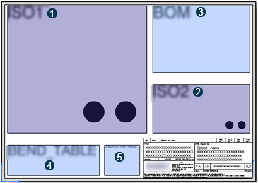
Isometric Piping Sheet Template Definition

Defining a sheet template in a drawing chapter with zone items containing the following names overrides the default content, and only defined content is created. In the sheet template, define the following items:

No. Items
View Item: ISO1 = view port for the isometric symbol view (mandatory).
View Item: ISO2 = view port for the isometric generative view (optional).
Table Item: BOM = location for the Bill-Of-Materials.
Table Item: BEND_TABLE = location for the Bend Data Table for bent pipes.

When the SIMPLE_BEND_TABLE tag is used in the sheet zone, a simplified bend data table is created. Additional features, such as angles, are shown in the bend radius annotation.

Table Item: ORIENTATION_TABLE = location for the Orientation table.

Support of View Templates for ISO2

You can use a view template attached in the ISO2 sheet zone for the ISO2 view. With this, you can customize view generated properties and use view update rules within the ISO2 view.

The isometric batch searches for the defined sheet template in the drawing profile, and then finds the corresponding ISO2 zone. If such a zone does not exist, the ISO2 view is not created within the ISO2 zone. A view template needs to be attached, which is then used during the computation of the ISO2 view.

Note: ISO1 view cannot be updated. To update the generated drawing, the ISO1 view needs to be locked.

To assign and modify a view template, you must delete and create the drawing again, as in the case for sheet templates.