Creating an Isometric Symbol

You can create a new 2D component and add it to the appropriate chapters.

Right-click the chapter and select Insert > Item: Feature.

Tip: Rename the 2D component's feature name to match the sub-type value of the part before adding it to the catalog chapter.

Note:

The name of the Catalog (For example, AITAC-ISO-CATALOG) and the name of the Chapter (For example, ISO-SYMBOLS) is pointed by the name (not as a link), by the Batch Resource: Piping ISOmetric Drawing profile, ISOCatalogName, and ISOSymbolChapterName.

The Batch reads the 3D object, and based on the Part sub-type, it maps the object to its corresponding 2D component. The mapping is done by the feature name in the chapter (For example, Flange Welding Neck). The entries in the Chapter point the 2D component features in a drawing.

See Also
Types of Isometric Symbols
  1. Open a drawing detail sheet, and create a standard 2D component.

    Note: Only line and circle elements are supported.

  2. To create a 2D component port, create a point and rename its Feature Name attribute to an appropriate port name (For example, Port1, Port2, and Port3).

    Note: It is mandatory that the new 2D component contains exactly the same amount of port definition as the mapped 3D object.
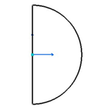
    The Port1 must be on the origin of the 2D component. The Port2 (if more than one port) is to be located with a positive X value.

    The distance between Port1 and Port2 is the relative symbol size.
  3. Optional: Modify the symbol size.

    For example, if the distance is 100 mm, the symbol is scaled according to the ISOSymbolSizeOnPaper.

    If the 2D component contains only one port, the symbol is assumed to be 100mm large (For example, a cap or a blind flange).