|
Define an Annotation Template
Follow this procedure to add annotations on your rebar drawing using Data Setup.
You can use a .3dxml template with the Catalog component type.
You can define your own template if you have the Multi-Discipline Drafting Template
role.
-
Create/Identify a resource file, for example Catalog.3dxml containing the
annotations' rules template definition for the rebars in a catalog.
It will be used as a Chapter resource type for the setting up procedure.
-
To import the resource file, select and the .3dxml file.
In the Import Option area of the dialog box, ensure that
Import As Ref is selected. For full instructions, see
3DEXPERIENCENative Apps: Importing and Exporting: Importing 3D XML
Files.
The 3D XML resource file is imported into the database.
-
Ask your Data Setup manager, or if you are granted the rights to use Data Setup
(Owner role) or, associate the resources to a collaborative space and add extensions
(Leader role), perform the procedure yourself:
-
Assign the Chapter resource file to the View
Update Rule Template in the related resource set table named
ASD Drafting resources.
The View Update Rule Template resource is displayed
under the ASD Drafting resource set.
-
Associate the resource set table, ASD Drafting resource,
to a collaborative space.
-
Click to save your changes.
-
Log out from the 3DEXPERIENCE.
-
Log in again to benefit from the Data Setup modifications. All changes made
through Data Setup will be shared with all actors working in the same collaborative
space.
Note:
If no template is assigned in the resource, no annotation is created by the
Rebar Drawing command, only 2D geometry appears in the
drawing.
Create a Rebar Drawing
You can generate a drawing from the rebar layers' geometry.
-
From the Building and Civil Assemblies
app,
open a product.
Note:
The 3DTag (for example on rebar layer 17) will be identical to the annotation text
you may generate in the 2D representation of the rebar layer. For more information,
see the last section.
-
Select its contextual command and click ASD Drawing.
The Multi-Discipline Drafting
app
opens.
-
From the View Layout section of the action bar,
select Front View and click a green plane in the 3D area of the
root product for projection. Click the 3D area to
create the view.
-
From the Civil Engineering section of the action bar,
click Rebar Drawing
 . .
All the layers are projected in this view and they are listed in the
Elements tab of the Rebar Drawing
dialog box. As bars are volumes, this is their layout that is projected into 2D.
The dialog box displays the following information:
- A combo box to select one or several layers and apply some preferences.
- Name: the name of the rebar layer.
- Group Prefix: name of the group of the bars. By default,
the proposed representation of the selected layer is the Single
Bar group. You can select another group representation. For
information , see the steps further down.
- Number: index of bars in the layer to be displayed.
- Status: status color codes
 : Numbering
and annotations are created successfully. : Numbering
and annotations are created successfully. : Drawing
view is not up-to-date. Click Apply to update it. : Drawing
view is not up-to-date. Click Apply to update it. : Numbering
is not launched or failed because the annotation template is not set/found. If
the template is changed, all the annotations created with the previous
template are deleted. To retrieve it, right-click Choose
Template on the No Template cell. : Numbering
is not launched or failed because the annotation template is not set/found. If
the template is changed, all the annotations created with the previous
template are deleted. To retrieve it, right-click Choose
Template on the No Template cell.
- Locked: the button is checked when the value is entered
manually in the Number column. And automatic numbering does
not change this value.
Change a 2D Layer Rebar Representation
You can configure different bar representations in the 2D view.
-
Select the Groups tab.
The dialog box contains a series of commands dedicated to the group management
of the bars, as detailed further down. The bar group types are detailed in the list with
the following columns:
- Prefix: name of the group.
- Definition: bar indexes from 1 to N.
N stands for the last bar index of the rebar layer. The
* symbol stands for all the bars.
- Template: the name of the template, when an Annotation Rule
Template has been defined.
Notes:
- A template is assigned to each group defined by default and, its name starts
with Single Bars Template or First and last bars
Template or All bars Template.
- If the template is replaced, all the annotations created with the previous
template are deleted. For more information, see the status color codes in the
previous section.
-
To automatically define the bar(s) that must be displayed in the drawing, select a
rebar layer in the list under the Elements tab.
-
Click the Move selected Element(s) to a Group command
 and select a
group in the list. and select a
group in the list.
- If Single bars is selected: the index of the bar at the
middle of the layer is proposed. The related definition is
N/2.
- If First and last selected: the index of the first and last
bars are proposed. The definition for this group is then set to 1,
N.
- If All bars selected: All the bar indexes are proposed. The
definition symbol for this group is *.
- Optional:
Enter manually the index of the bars in the Number
column:
-
- Single number, for example: 3 to display only the 3rd bar of the layer.
- Several numbers separated by a comma, for example: 3,8 to display both 3rd and
8th bar of the layer.
- * to display all the bars of the Layer.
- N to display the last bar of the Layer, for example: 1,N displays first and
last bar of the Layer.
Note:
If a value is entered manually in the Number column, the
value is locked (Lock column) so that the automatic numbering
does not change this value.
-
To refresh the Drawing view, take the numbering changes into account and display the
annotations, click Apply.
In the Groups tab, the three groups are available:
Single bars, First and last and
All bars. They cannot be modified nor deleted. Each cell in the
list is read-only.
-
To define your own group, click Create new group
 and do the
following: and do the
following:
-
A new line appears in the dialog box corresponding to the new group. Modify its
properties if needed: the Prefix (D by
default), the Definition (1 by
default) and, the Template (with the No Template
defined information in the cell).
-
Right-click No Template defined and select
Choose Template. The Catalog Browser
window opens.
-
Select the Unique Bar Template. This template also belongs
to the Catalog resource file. The cell information changes from No
Template defined into Unique bar
Template.
-
Click the Elements tab and
 to select
the D group (user-defined group) in the list. to select
the D group (user-defined group) in the list.
-
To reset the indexes of the bars that have been selected in the list, click
 . .
-
To clear the indexes of the bars that have been selected in the list, click

-
To remove the layers that have been selected in the list, click
 . If removed, the layers keep their default representation as volumes, no longer as
wires, and no annotations are created for them. . If removed, the layers keep their default representation as volumes, no longer as
wires, and no annotations are created for them.
-
To move selected layers from one group to another, click
 and select
another group in the list. and select
another group in the list.
-
Click Apply.
You obtain the 2D representation of the bars that are displayed as wires in the
drawing.
If you select  , only one bar
is displayed by default for each layer selected in the list. Small black disks
symbolize the bends' location. , only one bar
is displayed by default for each layer selected in the list. Small black disks
symbolize the bends' location.
As explained in the first section above, an annotation rule template can be created
to define your rebar annotations. Annotations appear along rebar drawings.
The bars to be displayed can be modified and the annotation is changed accordingly by
clicking Apply.
Depending on the selected group, you obtain a different 2D representation:
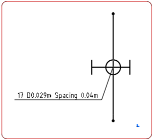
| Single bars |
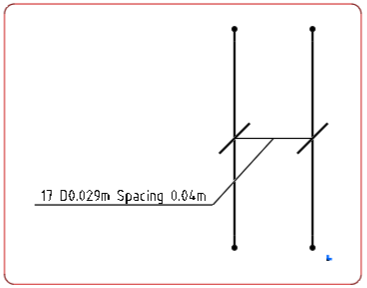
First and last bars |
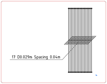
All bars |
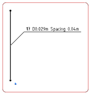
User-defined Group |
 |
 |
 |
 |
| The representation displays only the middle bar of the layer. The
intersection is symbolized by a circle and, an annotation text is connected to
the bar. A segment represents the width of the rebar layer. Small black disks
stand for the bendings. |
The representation displays only the first and last bars of the layer
and, a double leader annotation is created. |
All the bars are projected into the drawing. With this symbol  , you can visualize the intersections. , you can visualize the intersections. |
As defined by default, representation displays only the first bar with
its annotation. |
Notes:
- The annotation indicates the number of bars in the layer (for example: 17), the
spacing between the bars (for example: 0.04m) and, the bar mark number when it
exists.
- The text of the annotation is the text of the 3DTag defined in the 3D design. If
you customize the 3DTag, the 2D annotation is synchronized with the same text.
-
To manipulate the annotations in the 3D area, click
OK and do the following:
-
Select the annotation text.
-
Move the double-headed arrow manipulator
 under the
annotation. under the
annotation.
|


 , you can visualize the intersections.
 under the
annotation.