The first selection determines the support mode. This mode cannot be
changed. A free edge stiffener created on an opening can only accept another
opening as a support.
Limits
You can specify start and end limits to the stiffeners. For more
information about limits, see
About Profile Limits.
Next Solution
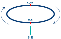
The Next Solution button is available only when there are multiple possible solutions for the selected limits and support. It lets you switch from one solution to the next.
Possible solutions: S1-E1, S1-E2, S2-E1, S2-E2
S: Start limit, E: End limit
The solutions are computed considering the orientation of the delimited trace. You can click Swap Ends to swap the limits and thus to invert the orientation of the trace.
Recommendation:
Use this functionality only when you have selected a common limiting element for start and end limits, as shown in the above image.
Orientation
You can orient the stiffener as explained below:
Plate Side and Section Orientation
You can
Flip the
Plate Side and
Section Orientation to get the correct
orientation. The images below show both operations.
Anchor Point and Anchor Point Offset
The anchor points displayed in the
Anchor Point box are defined in the molded
convention resource that is set in
Data Setup. If no molded convention resource is set in Data Setup, the default list of anchor points will be available.
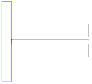
Anchor point offset allows you to modify
the location of the anchor point of a face plate stiffener.
Changing the offset value moves the stiffener more to one side
or the other. The images below show a stiffener that is not offset (left) and
one that has been offset.
A stiffener with zero offset.
A stiffener with offset.
Important:
Thickness is shown for
visualization purpose in the image above. You cannot see thickness in the
Structure Functional Designapp.