Built-In Endcut Parameters | ||
| ||
About Built-In Endcuts
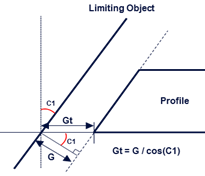
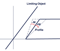
Built-in endcuts correspond to the algorithm that provides a simple plane which is computed from a cutback plane and given built-in parameters such as G, Gt, and M.
You can create an endcut table that lists the endcut name, type, name of the corresponding bitmap image, applicable limit type, and graphic primitive attributes. Then set it in the Structure Resource table of the Data Setup.
Recommended Parameters
The built-in endcut parameters are defined in the endcut reference.
For the web element of the profile, following parameters are taken into
account:


- G
- Gap between the cutback plane and the end cut measured along the normal to the cutback plane.
- Gt
- Gap between the cutback plane and the end cut measured along the trace of the profile.
- C1
- Computed angle from the cutback plane.
- M
- Snipe angle.
Note:
The endcut in
Structure Functional Design
can have all parameters and attributes as defined in for the
Structure Design
built-in endcut.