Creating a Web Girder | |||
| |||
- From the Function section of the action bar, click Panel
 .The Panel dialog box appears.
 -
In the Category box, select a category of the panel.
Note: If no dictionary is set in Data Setup, only the default category is available.
- Optional: Clear the Automatic check box and type the required name in the Name box.Note: If an action rule is set in Rules Catalog or Rules Library in Data Setup, and if you retain the selection of the Automatic check box, the name is automatically assigned to the structural object as per naming action rule. For more information, see Action Rule for Naming.
-
Click the Material and Orientation tab and enter the
details.
For more information, see Material and Orientation Tab.
-
In the Geometry tab, select cross planes as support for the girder
in the Support box.
You can select the support in the work area or by right-clicking in the Support box, and choosing Select Reference Plane.
Warning: It is important to select a support that is compatible with the selected category. - Optional: In the Offset box, enter the required value by which thepanel should be offset from the support.
- Select reference planes as limiting objects, to trim the excess plate.The selected limits appear in the Limit area.
Tips: You can: - Click Switch Side to toggle between the sides you want to limit.
- Click Remove to remove the selected limit.
- Click Replace to replace the existing limit with another limiting element.
- Click Sketcher
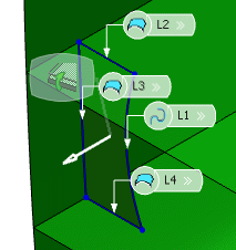
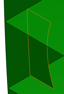
 .The Sketcher app opens with the support object selected as the sketch plane. Draw a limit to the web girder. The image below shows part of the hull and the web girder, with a line drawn at the location where it will be limited.
- In the Offset column, enter the required offset value for each limiting element.
- Click OK.The girder is created.
