About Additive Manufacturing

3D printing offers the ability to produce complex designs impossible to create with traditional manufacturing methods. This section describes options for simulating the manufacturing process and its impact on a design.

This page discusses:

Additive manufacturing (AM), also referred to as 3D printing, is a broadly used term to describe industrial processes for manufacturing which three-dimensional objects through:

  • A controlled deposition of powdered or liquid raw material.
  • Induced transformation into a solid state.
Additive manufacturing makes it easy to produce complex shapes. Because it eliminates many of the traditional manufacturing constraints, the functional requirements of the part become the primary focus of the design effort. However, additive manufacturing processes have their own challenges. For example, thermal effects during manufacturing can produce residual stresses that can lead to failure during manufacturing or during the in-service life of the part.

The goals of an additive manufacturing simulation are as follows:

  • Predict residual stresses in the part.
  • Minimize the gap between the designed and manufactured part through process optimization.
  • Evaluate how the manufactured part performs under realistic loading conditions in an assembly with other components.

Additive Manufacturing Scenario Creation

Additive Manufacturing Scenario Creation simulates two classes of additive manufacturing processes: powder bed and direct material deposition.

In a powder bed–type additive manufacturing process, like selective laser sintering (SLS) and stereolithography (SLA), a recoater or a roller blade deposits a single layer of raw material. Then, a high-powered laser scans a single cross-section of the part over the layer of raw material to fuse it with the previous layer underneath. The raw material deposition layering is simulated by progressive element activation in a structural or a thermal analysis. The laser-induced heating is simulated by a moving heat flux in a thermal analysis.

In direct material deposition, the raw material and heat source are applied at the same time and location. In a fusion deposition modeling (FDM)-type additive manufacturing process, the raw material is injected through a nozzle onto a platform. The nozzle traces the pattern for each layer with the raw material. Materials are typically deposited layer by layer until the build is complete. The raw material can be deposited in a molten state that hardens as it cools. In some processes, such as laser direct energy deposition (LDED), the raw material is injected in a powdered form and then heated in place by a laser beam.

Additive Manufacturing Scenario Creation also supports two different simulation workflows for additive manufacturing processes, thermomechanical and eigenstrain-based.

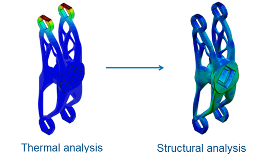
A thermomechanical simulation consists of a transient heat transfer analysis of thermal loads introduced on a part during the printing process. The thermal analysis is followed by a static structural analysis that is driven by the temperature field from the thermal analysis. The simulation allows exact specification in time and space of processing conditions and gives you precise control over the fidelity of the solution. The simulation is accurate and comprehensive, but it can be computationally expensive with increasing time and spatial (mesh) resolution.

Consider the aspects of the process in the thermal and stress simulations. For the heat transfer (thermal) analysis:

  • Progressive material deposition: every additive manufacturing process adds new material with time, changing the thermal profile of the model.
  • Progressive heating of the deposited material: for some additive manufacturing processes, the newly deposited layer of material is heated to the melting point, causing the material to fuse to an underlying layer or a substrate.
  • Progressive cooling of the printing part: as a part is printed, its cooling surface is continuously evolving with time.

For the stress analysis:

  • Temperatures from the heat transfer analysis drive the stress analysis.
  • Progressive material deposition requires similar techniques as those used in the heat transfer analysis.
  • Temperature-dependent material properties can be used to produce accurate stress results.


The eigenstrain-based processes uses eigenstrains, or inherent strains. Eigenstrain is an engineering concept used to account for all possible sources of permanent (or inelastic) deformation induced by the process. Eigenstrain has long been used for the evaluation of residual stresses from welding operations. An eigenstrain-based simulation of an additive manufacturing process consists of a single static stress analysis of a printing part. A predefined eigenstrain field is applied according to an element activation sequence representative of the process (usually layer by layer). This process results in a distribution of residual stresses and a deformation field that can lead to the overall distortion of the part. This method eliminates the need to obtain detailed machine information; however, it requires that you calibrate eigenstrain values from experiments or detailed process-level thermomechanical simulations. The results from an eigenstrain-based simulation are typically more approximate than a thermomechanical simulation. Generally, the eigenstrain analysis is sufficient to capture distortion and residual stresses. However, it might not capture higher-order deformation modes, such as the buckling that can happen in thin-walled components during printing.

Additive Manufacturing Scenario Creation can work independently or incorporate data from the Powder Bed Fabrication app. Using data from Powder Bed Fabrication helps tie the simulation to your additive manufacturing process. It also supports options such as the use of perforated supports. For simulation, perforated supports are modeled as solids with the mass, stiffness, and thermal conductivity automatically scaled down to account for the perforation data.

Additive Manufacturing Scenario Creation provides four different options for simulating an additive manufacturing process. Three of the options are for powder bed-type AM processes, and the fourth is for FDM- and LDED-type AM processes:

  • Thermal-Mechanical For Powder Bed
  • Eigenstrain For Powder Bed
  • Pattern Based Thermal-Mechanical For Powder Bed
  • Thermal-Mechanical For FDM/LDED

Thermal-Mechanical Simulation of a Powder Bed Process

This process uses a sequential thermal-mechanical analysis and allows you to precisely define the material deposition, moving heat source, and cooling conditions in a powder bed additive manufacturing process. It is the most accurate powder bed approach available but can be computationally expensive. You need toolpath trajectories of the recoater and the laser to define the material deposition and heating sequences.

You can simulate the layer by layer material deposition by using progressive element activation in both the structural and the thermal analysis. A moving heat flux in the thermal analysis simulates precise laser-induced heating. You can approximate the laser as a concentrated moving heat flux, a uniformly distributed heat flux over a boxed-shaped volume, or a heat flux based on a Goldak distribution.

Pattern-based Thermal-Mechanical Simulation of a Powder Bed Process

The pattern-based approach uses a sequential thermal-mechanical analysis to simulate a powder bed additive manufacturing process. It does not usually provide the level of control and fidelity of a trajectory based thermal-mechanical simulation; however, the pattern-based approach is easier to set up and less computationally expensive. It is typically more accurate than an eigenstrain-based simulation.

In the pattern-based approach, instead of precisely describing the individual trajectories of a laser, you define a repeated scan pattern over the part that represents an idealized motion of the laser (or other heat source). In the simulation, one or more layers of elements are typically activated in the same time increment, which reduces the overall simulation time.

Eigenstrain-based Simulation of a Powder Bed Process

The eigenstrain-based simulation uses a single static procedure. This process is typically more approximate than the sequential thermal-structural simulations, but the simulation is generally faster to solve.

In an eigenstrain analysis, you apply a predefined field of strains to the part in a static procedure. The eigenstrains, also referred to as inherent strains, lead to an internal stress field that represents a residual stress field caused by the manufacturing process. For more information, see Eigenstrain Additive Manufacturing Workflow.

Thermal-Mechanical Simulation of FDM and LDED Processes

The direct energy deposition process uses a sequential thermal-mechanical analysis and allows you to precisely define the material deposition, moving heat source, and cooling conditions in fusion deposition modeling (FDM) or laser direct energy deposition (LDED) additive manufacturing processes.

The deposition of raw material, laid down in beads, is simulated by progressive element activation in both the structural and the thermal analysis. For an FDM process, you simulate the heating by prescribing an initial temperature (above melting temperature) for the raw material. For an LDED process, you define a moving heat flux in a thermal analysis to simulate the precise laser-induced heating. You can choose to approximate the laser as a concentrated moving heat flux, a uniformly distributed heat flux over a boxed-shaped volume, or a heat flux based on a Goldak distribution.

Controlling the Scale of the Simulation and the Solution Fidelity in a Thermal-Mechanical Simulation

Additive manufacturing process simulation is a multiscale problem in both time and space. You can control the scale of the simulation and the solution fidelity by choosing an appropriate time incrementation scheme and mesh size. In general, you can consider the following simulation types, which are at different ends of the fidelity spectrum: process-level simulations (high fidelity) versus part-level simulations (lower fidelity).

You create a detailed process-level simulation by using a small time increment and fine meshes with at least one element per printing layer thickness and a few elements across an action zone where active melting or fusion occurs. The simulation captures the rapidly evolving temperature and high-temperature gradients typically found within and near action zones, therefore, it provides accurate predictions for both residual stresses and distortions. You can specify temperature-dependent thermal and mechanical material properties. You can model thermal energy release and absorption during melting and solidification in heat transfer analyses using latent heat definitions. A process-level simulation can model detailed physics of additive manufacturing processes and provide accurate results; however, it typically has a high computational cost and can be affected by convergence difficulties due to the use of temperature-dependent nonlinear material properties under rapidly changing temperature conditions.

You create a part-level simulation by appropriately averaging (lumping) the time sequence of events and using relatively coarse meshes. For example, the model could have an element size that is a few times larger than the printing layer thickness and use only one or several time increments for printing one element layer. The heat transfer analysis can usually capture far-field temperature evolutions (away from action zones) as long as you carefully model the thermal energy balance of progressive heating and cooling. However, a part-level simulation might not capture local rapid temperature evolutions properly because the specified sequence of concentrated, fast-moving heat sources is lumped over both time and space. In other words, the temperature results do not usually contain an accurate history of melting and solidification. To model the annealing or melting effects in the stress analysis correctly, you must assign an initial temperature representing a relaxation temperature above which thermal straining induces negligible thermal stress in the printing part. Upon element activation, the relaxation temperature is the temperature from which the initial thermal contraction occurs. You can calibrate the relaxation temperature from experiments or from detailed process-level simulations. The part-level simulation is computationally efficient for the prediction of distortions and stresses in printing parts with reasonable accuracy.