Eigenstrain Additive Manufacturing Workflow | |
| |
A typical workflow for an eigenstrain additive manufacturing analysis is outlined below. Each step corresponds to the sections displayed in the Assistant.
| Tip: Use the standard area of the action bar to activate the Assistant if it has been closed. |
Before you begin: Position the model within the workspace.
- Setup the model.
- Create or select a finite element model.
- Assign separate mesh sizes for the build geometry, the build tray, and the supports.
- Define the shell thickness for the supports.
- Create the
Meshes.
- Create meshes for the printed parts, supports, and the build
plate.
The app automatically generates meshes for parts and supports that have associated slicing and scanning information and for the build plate.
- Select additional meshing algorithms, if required.
- Create meshes for the printed parts, supports, and the build
plate.
- Define the
Part & Support Properties.
- Assign section properties to the model.
The app creates section properties automatically if there is existing slicing data.
- Connect the different parts together. Create tie connections between the part, supports, and the build tray.
- Assign section properties to the model.
- Define an
Eigenstrain Library.
Choose a library that contains the strain patches used to represent the buildup of layers in the additive manufacturing simulation. For more information, see About Additive Manufacturing Libraries.
- Specify the
Eigenstrain Assignment to define how the
material is activated.
Material is activated as it is deposited on the part by the manufacturing process. The material activation includes a reference to the library data and instructions for how the data is used to produce the model.
- Define an eigenstrain time constant to ramp up eigenstrains at
element activation.
Applying the eigenstrains gradually can aid in solution convergence, especially if there is plasticity in the model. The default time constant is zero.
- Define a build coordinate system.
The coordinate system is used as a reference for the build direction (local direction 3), the eigenstrain patterns, and the scanning regions in which eigenstrain patterns are assigned.

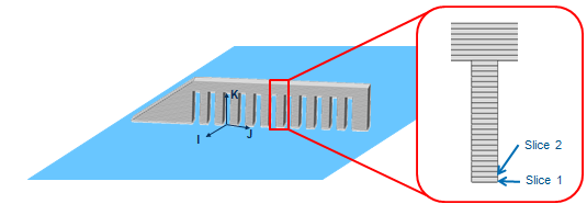
- Assign the slice thickness.
The slice thickness partitions the model into of slabs (slices) of uniform thickness along the build direction. The slicing starts from the base of the part.
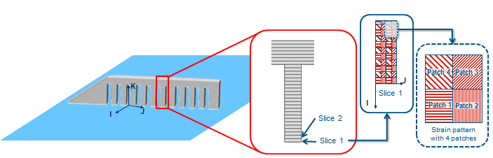
- Define one or more eigenstrain patterns.
An eigenstrain pattern is a rectangular domain that is partitioned by a "quilt" of one or more patches. A patch is a rectangular area that is assigned both an eigenstrain and a local rotation of the eigenstrain. You assign the height and width of each patch. Ensure that the assigned sizes and locations of the patches completely fill a rectangular area and that the patches do not overlap. For more information, see About Additive Manufacturing Libraries.
- Define a scan region in which the eigenstrain patterns are
applied.
A scan region is a rectangular cuboid whose sides align with the build coordinate system. Define a set of one or more nonoverlapping scan regions that completely enclose the additive manufacturing model. A single eigenstrain pattern is assigned to each scan region.
Note: An eigenstrain pattern can be assigned to multiple scan regions, and every pattern can be rotated by a fixed angle for each successive slice in the build direction.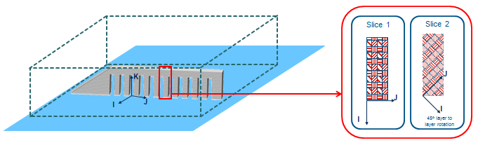
- Define an eigenstrain time constant to ramp up eigenstrains at
element activation.
- Create
Structural Restraints & Loads.
- Apply restraints to prevent rigid body motion of the part in the
structural analysis.
A clamp restraint is sufficient since there are no in-service loads being applied during the manufacturing simulation.
- Apply restraints to prevent rigid body motion of the part in the
structural analysis.
- Simulate.
- If required, perform checks before solving the simulation.
- If required, configure the simulation options, including selecting local or remote execution.
- Start the solve.
You can check or run just the thermal simulation or both the thermal and structural simulations.
- Postprocess the
Results.
- Create plots and visualize results.
For example, you can create contour plots that display results using a spectrum of colors with corresponding values.
- If required, create sensors, which can be used in external simulations.
- Create plots and visualize results.