About Axisymmetric Simulations | |
| |
Axisymmetric Model and Feature Basics
You can use axisymmetric model generation to create a three-dimensional model and associated simulation features by revolving a two-dimensional representation of the geometry and features about its axis of revolution. An axisymmetric model and its simulation features is much simpler to define than the corresponding 3D model and features. As a result, the axisymmetric simulation provides substantial savings in simulation processing time compared to a similar solid model. The simulation is run in two dimensions, and the results are shown in 2D. However, you can sweep the results about the axis to produce a 3D view.
To create an axisymmetric model, you use the Automated FEM tool in Model Assembly Design to cut the 3D model and create the 2D representation. For more information, see Model Assembly Design: Creating an Axisymmetric FEM.
Because symmetry is used to create a 3D model from a 2D representation, it is helpful to consider every piece of the axisymmetric simulation as being reduced by one dimension. A planar model is swept about the axis of symmetry to become a solid or a 3D shell; an edge creates a surface, and a point creates an edge. The loads, boundary conditions, and other features work in the same way. For example, you apply a pressure load to surfaces in 3D simulations. In an axisymmetric simulation, you apply a pressure to a 2D edge that becomes a surface in the rotated model. Likewise, you apply a solid section to a solid body, but in an axisymmetric model the solid body is represented as a 2D surface. Apart from this change in dimensionality, most features for axisymmetric models work identically to those for a regular 3D simulation. The X- and Y-axis for a Cartesian coordinate system become the R- and Z-axis for the cylindrical system, with rotated about the Z-axis. If you select a local coordinate system for a feature, you must choose an axis system whose X-Y plane corresponds to the R-Z plane of the axisymmetric model.
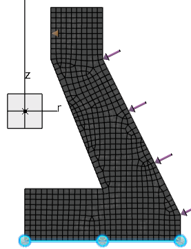
The image below shows an axisymmetric model with a clamp restraint applied to the bottom
edge (parallel to the R-axis) and a pressure load applied to the angular outer edge. In the
3D model, the clamp is applied to a circular face and the pressure load to a conical face
created by rotating the 2D representation. 
The model and scenario views of axisymmetric simulations always show the 2D representation. However, you can create a results view that sweeps the planar model and results through an angle to show the 3D view.
Axisymmetric Finite Element Models
There are several ways that you can create the finite element model to use for an axisymmetric simulation. You can begin with a 3D model, a 2D planar model, or start with an empty FEM and create the required geometry. In each case, you must select a plane, model origin (point), and an axis (line) to define the symmetry of the model. (You can create them using selections from the context menu, if needed.)
In the first case, you extract a 2D view from a 3D model. This means you already have the complete 3D geometry and are producing a simplified FEM for simulation. The FEM is created by cutting the 3D model through the plane and extending outward from the axis to the edge of the model in that plane. You can choose the geometry that is included for the definition. For example, your 3D model might include geometry that is not symmetric or bodies that are not required for the simulation. You can also initialize a default mesh or modify basic mesh parameters to control the mesh so you are ready to add simulation features in a scenario app.
In the second case, you specify an existing 2D planar model. You must already have a 2D surface or wireframe that, when rotated, produces a 3D solid or shell. Like the extracted case, you can choose whether to create a default mesh or to modify basic mesh parameters and then create a mesh.
In the final case, you have no geometry, and you create an empty FEM. To make use of this method, you must still have a plane, an origin, and an axis; you must also have the means to create geometry for the planar symmetry model.
Supported Procedures and Apps
Axisymmetric simulations are available only when you use the following model and scenario apps:
- Structural Model Creation
- Mechanical Scenario Creation
- Structural Scenario Creation
You can use the following step types for axisymmetric simulation:
- Static
- Static Perturbation
- Frequency
- Implicit Dynamic
- Explicit Dynamic