About Steps and Analysis Procedures

The step sequence in a simulation scenario provides a convenient way to capture changes in the loading and boundary conditions of the model. In addition, steps enable you to change the analysis procedure, the data output, and various controls.

This page discusses:

Step Types

The set of available step types and their behavior depends on whether you are creating a structural simulation or a fluid simulation.

Step Types in Structural Simulations

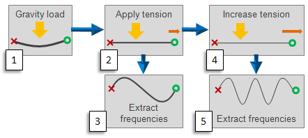
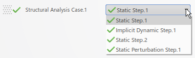
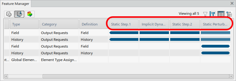
All simulation steps in structural analyses are either general analysis steps or linear perturbation steps.

General analysis steps define sequential events: the state of the model at the end of one general step provides the initial state for the start of the next general step. Each general analysis step has its own step time that contributes to the overall time of the simulation. General analysis steps can account for the effects of nonlinearities present in the model.

Linear perturbation steps provide the linear response of the model about the state reached at the end of the last general nonlinear step. Linear perturbation steps have no step time associated with them (or the time is assumed to be an arbitrarily small number), and they do not contribute to the overall time of the simulation. Linear perturbation steps do not account for nonlinearities of any sort.

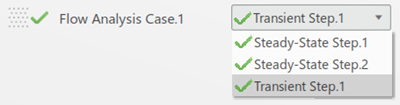
Step Types in Fluid Simulations

Fluid simulations also support the creation of multiple general analysis steps to simulate a sequence of events. There are two types of steps in a fluid simulation: steady-state flow steps and transient flow steps. As in structural simulations, each step has its own step time, and the state of the model at the end of one step provides the initial state for the start of the next step.

Analysis Procedures

Each simulation step is associated with a particular analysis procedure. The analysis procedure is synonymous with the type of simulation performed. By extension, the step determines which scenario features you can apply to the model and what output is available from the simulation.

Step Sequencing

Step sequencing behaves differently in structural simulations than in fluid simulations because structural simulations include linear perturbation steps.

Step Sequencing in Structural Simulations

Within any general analysis step, you can use the step time along with amplitude definitions to control the application of loads in a simulation scenario. However, for significant changes to loading, restraints, or output requests, creating multiple steps is often convenient. Each step can include its own set of loads, restraints, output requests, etc. The state of the model (stresses, strains, temperatures, etc.) is updated throughout all general analysis steps. The effects of previous steps are always included in the response for each new analysis step. The time for each individual step accumulates in the total simulation time.

You can change the analysis procedure from step to step in any meaningful way, so you have great flexibility in performing analyses. Linear perturbation steps, however, have no effect on subsequent general analysis steps; the starting condition for a general analysis step is the ending condition from the last general analysis step. The starting condition for a linear perturbation step is also the ending condition from the last general analysis step (also called the "base state"). Therefore, for example, if a frequency step is performed after a static step, the preload stiffness will be included in the frequency calculation. You can perform linear perturbation analyses from time to time during a fully nonlinear scenario by including the linear perturbation steps between the general analysis steps, as shown below.

There are some step types that you cannot combine in the same simulation; for example, the analysis procedure associated with an explicit dynamic step is not compatible with the implicit analysis procedures associated with other step types. Therefore, you cannot combine an explicit dynamic step with any other step type in a simulation (though you can have multiple explicit dynamic steps in the same simulation).

Step Sequencing in Fluid Simulations

The Fluid Scenario Creation app also offers great flexibility for step definition, enabling you to create multiple steps to simulate significant changes in boundary conditions, physics behavior, or output requests in fluid analyses. For example, you can perform a transient simulation first with a rather large time step to drive the physics quickly to the stage in which you are interested. Then you can perform a add a second step with a much smaller time step and rerun your simulation to capture all the details of the physical phenomena. You can also combine a steady-state simulation step with a transient simulation step.

Feature Propagation

You create a feature in a specific step, and it is then active (or propagated) in all subsequent steps. For example, if you place a weight on a beam in the first step of a scenario, the weight remains on the beam for all subsequent steps.

Some features can be modified in propagated steps using one of two techniques:

  • If the feature includes an amplitude reference, a new amplitude can be assigned to the feature in propagated steps.
  • The feature can be deactivated entirely.

Other components of the feature definition cannot be edited in propagated steps. Certain steps do not even allow deactivation of propagated features; for example, a propagated load cannot be deactivated in a frequency step because that would invalidate the preloaded base state of that step.

You can review the propagation of features in the Feature Manager, which provides a visual representation of the steps when each feature was created, propagated, or deactivated.

Working with Steps

You can create and edit simulation steps using commands in the Procedures section of the action bar. Step definitions can also impact other actions and features in a scenario.

To create a new step, click the icon for the desired step type and fill out the resulting dialog box.

As you create multiple steps, they appear in the context selector in the work area. The steps are listed sequentially from top to bottom. The images below show the appearance of the context selector for simulations in Structural Simulation and in Fluid Scenario Creation.

Structural Simulation

Fluid Scenario Creation

If your simulation has more than one analysis case, each has its own set of steps.

You can see the sequence of steps in the Feature Manager, as shown in Figure 1. The four steps in Structural Analysis Case.1 above appear as columns in the Feature Manager, and the graphical display shows how features propagate through steps.

Sequence of Steps for a Structural Simulation