Continuum Elements

Continuum or solid elements can be used to model the widest variety of components. Conceptually, continuum elements simply model small blocks of material in a component.

Since they might be connected to other elements on any of their faces, continuum elements, like bricks in a building or tiles in a mosaic, can be used to build models of nearly any shape, subjected to nearly any loading. There are stress/displacement, nonstructural, and coupled field continuum elements; this guide will discuss only stress/displacement elements.

This page discusses:

Three-dimensional continuum element library

Three-dimensional continuum elements can be hexahedra (bricks), wedges (triangular prism), or tetrahedra.

Example of three-dimensional continuum elements

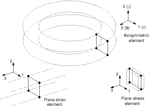
A library of solid elements also includes two-dimensional elements. The most commonly used two-dimensional continuum elements are as follows:

  • Plane strain elements suitable for modeling thick structures (out-of-plane strain is zero); for example, a cross-section of a dam under water pressure.
  • Plane stress elements suitable for modeling thin structures (out-of-plane stress is zero); for example, thin slabs with one dimension smaller than the other two.
  • Axisymmetric elements suitable for analyzing structures with axisymmetric geometry subjected to axisymmetric loading; for example, an O-ring pressed into a groove by a top plate.
Plane strain, plane stress, and axisymmetric elements

Selecting Continuum Elements

The correct choice of element for a particular simulation is vital if accurate results are to be obtained at a reasonable cost.

If you are a new user with little experience of FEA applications, the task of selecting the most suitable element is usually executed by the software. The most commonly used element for meshing arbitrary geometries is the quadratic tetrahedron. As you become more experienced with FEA applications, you can follow these recommendations on element selection:

  • Minimize the mesh distortion as much as possible. Coarse meshes with distorted linear elements can give very poor results.
  • Use a fine mesh of linear, reduced-integration elements for simulations involving very large mesh distortions (large-strain analysis).
  • Use quadratic, reduced-integration elements for general analysis work, unless you need to model very large strains or have a simulation with complex, changing contact conditions.
  • Use quadratic, fully integrated elements locally where stress concentrations might exist. They provide the best resolution of the stress gradients at the lowest cost.
  • For contact problems use a fine mesh of linear, reduced-integration elements.