Finite elements are the fundamental components of an FEA model. They are basic geometric shapes that discretize the model geometry and are represented mathematically by element equations. The element equations are simple equations that locally approximate
the original complex equations of the problem to be analyzed.
Each finite element is characterized by the following:
Depending on the geometry features of the model, you assign elements from a suitable element family to create the mesh.
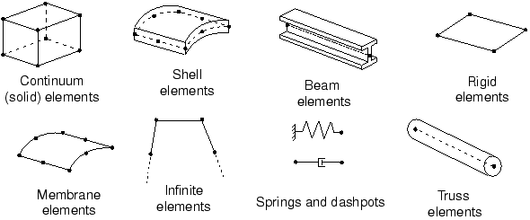
Commonly used element libraries for a stress/displacement simulation include: continuum (or solid), shell, beam, truss, rigid elements, etc.
Common element families
Degrees of freedom (directly related to the element family)
The degrees of freedom (dof) are the fundamental variables calculated during the analysis.
For a stress/displacement simulation the degrees of freedom are the translations at each node. Some element families, such as the beam and shell families, have rotational degrees of freedom as well. For a heat transfer simulation the degrees of freedom are the temperatures at each node.
Note:
A heat transfer analysis, therefore, requires the use of different elements
than a stress analysis, since the degrees of freedom are unequal.
Depending on the type of analysis, the calculated degrees of freedom are:
Three translations in the -, -, and -directions (based on a global or local coordinate system)
Three rotations about the -, -, and -axes (based on a global or local coordinate system)
Warping in open-section beam elements
Acoustic pressure, pore pressure, or hydrostatic fluid pressure
Electric potential
Temperature
Number of Nodes - order of interpolation
Displacements, rotations, temperatures, and any other degrees of freedom mentioned in the previous section are calculated only at the nodes of the element.
At any other point in the element, the displacements are obtained by interpolating from the nodal displacements. Usually the interpolation order is determined by the number of nodes used in the element.
Linear or First-Order elements
Elements that have nodes only at their corners use linear interpolation.
Quadratic or Second-Order elements
Elements with mid-side nodes use quadratic interpolation
Modified or Modified Second-Order elements
Modified triangular or tetrahedral elements with mid-side nodes use a modified second-order interpolation.
In general, for the same mesh density (number of elements), quadratic elements yield better results than linear elements because they represent curved boundaries more accurately and produce more accurate mathematical approximations.
Linear brick, quadratic brick, and modified tetrahedral elements
Formulation
An element's formulation refers to the mathematical theory used to define the element's behavior.
In the absence of adaptive meshing all of the stress/displacement elements are based on the Lagrangian or material description of behavior: the material associated with an element remains associated with the element throughout the analysis, and material cannot flow across element boundaries.
In the alternative Eulerian or spatial description, elements are fixed in space as the material flows through them. Eulerian methods are used commonly in fluid mechanics simulations.
Some element formulations allow coupled field problems to be solved. For example, there are elements that possess both mechanical and thermal degrees of freedom and are intended for coupled thermal-mechanical simulations. Moreover, to accommodate different types of behavior, some element families include elements with different formulations. For example, the shell element family has three classes: one suitable for general-purpose shell analysis, another for thin shells, and yet another for thick shells.
Note:
Adaptive meshing combines the features of pure Lagrangian and Eulerian analyses and allows the motion of the element to be independent of the material. Eulerian elements and adaptive meshing are not discussed in this guide.
Integration
The term integration refers to numerical techniques, like Gaussian quadrature, to integrate the polynomial terms in an element's stiffness matrix, over the volume of each element.
Using Gaussian quadrature for most elements, an FEA solver evaluates the material response at each integration point in each element. Some elements can use full or reduced integration, a choice that can have a significant effect on the accuracy of the element for a given problem.
Integration points in fully integrated, two-dimensional, quadrilateral elements
Integration points in reduced integrated, two-dimensional, quadrilateral elements
The expression "full integration" refers to the number of Gauss points required to integrate the polynomial terms in an element's stiffness matrix when the element has a regular shape. For hexahedral and quadrilateral elements a "regular shape" means that the edges are straight and meet at right angles and that any edge nodes are at the midpoint of the edge.
Reduced-integration elements use one less integration point in
each direction than fully integrated elements.
Reduced-integration, linear elements have just a single integration
point located at the element's centroid.
Quadratic reduced-integration elements are generally the best choice for most general stress/displacement simulations, except in large-displacement simulations involving very large strains and in some types of contact analyses.