Mesh Quality Checks | ||
| ||
Aspect Ratio Checks
Numerical accuracy is best achieved by a mesh with uniform size elements whose edges are equal in length. For most CAD geometries, due to the existence of small edges, curvature changes, thin features, and sharp corners, it is impossible to create a mesh of perfect elements with equal lengths.
The aspect ratio of a perfect, tetrahedral element is used as the basis for calculating aspect ratios of other elements. By definition, the aspect ratio of a perfect tetrahedral element is 1.0. Finite elements provide more accurate results when their aspect ratio is close to 1.0. When the lengths of an element edges differ significantly, the accuracy of the results deteriorates.
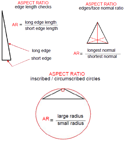
There are different ways to measure the aspect ratio of an element:
- The ratio of the longest to the shortest element edge.
- The ratio of the longest normal to the shortest normal dropped from a vertex to the opposite face.
- The ratio of the largest circumscribed circle to the smallest inscribed circle.

Jacobian Check
Second-order elements map to curved geometry more accurately than linear elements of the same size. The mid-side nodes of the boundary edges of an element are placed on the actual geometry of the model. At the location of sharp or curved boundaries, placing the mid-side nodes on the actual geometry can result in generating distorted elements with overlapping edges.
The Jacobian ratio at a point inside the element provides a measure of the degree of distortion of the element at that location. Parabolic, tetrahedral elements with all mid-side nodes located exactly at the middle of the edges have a Jacobian ratio of 1.0. The Jacobian ratio increases as the curvatures of the element edges increase. A highly distorted element has a negative Jacobian ratio. It is a good practice to avoid these elements with "concave" faces by applying mesh controls or by adjusting the global element size.