Rigid Bodies | ||
| ||
The main advantage of representing portions of a model with rigid bodies is computational efficiency. Element-level calculations are not performed for elements that are part of a rigid body. Although some computational effort is required to update the motion of the nodes of the rigid body and to assemble concentrated and distributed loads, the motion of the rigid body is determined completely by a maximum of six degrees of freedom (three translations and three rotations about the , , and directions) at the rigid body reference node.
It might be useful to make parts of a model rigid for verification purposes. For example, in complex models elements far away from the particular region of interest could be included as part of a rigid body, resulting in faster run times at the model development stage. When you are satisfied with the model, you can remove the rigid body definitions and incorporate an accurate deformable finite element representation throughout.
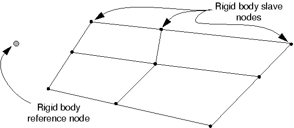
Only the rigid body reference node has independent degrees of freedom and must be defined for every rigid body.
The nodes attached to rigid elements have only secondary degrees of freedom. The motion of these nodes is determined entirely by the motion of the rigid body reference node. Nodes that are part of a rigid body are one of two types:
- Pin nodes, which have only translational degrees of freedom.
- Tie nodes, which have both translational and rotational degrees of freedom.
Loads on a rigid body are generated from concentrated loads applied to nodes and distributed loads applied to elements that are part of the rigid body or from loads applied to the rigid body reference node. Rigid bodies interact with the rest of the model through nodal connections to deformable elements and through contact with deformable elements.