Shell Elements

Use shell elements to model structures in which one dimension (the thickness) is significantly smaller than the other dimensions, and in which the stresses in the thickness direction are negligible.

Shell elements are 2D elements capable of resisting membrane and bending loads. A structure, such as a pressure vessel, whose thickness is less than 1/10 of a typical global structural dimension generally can be modeled with shell elements. The following are examples of typical global dimensions:

  • Distance between supports
  • Distance between stiffeners or large changes in section thickness
  • Radius of curvature, and
  • Wavelength of the highest vibration mode of interest.

The following topics are discussed:

This page discusses:

Element Geometry

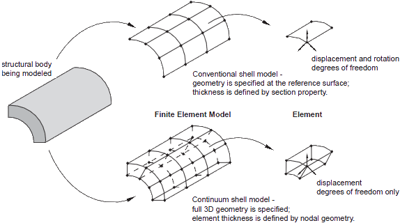
Conventional shell elements (2D elements) discretize a reference surface by defining the element's planar dimensions, its surface normal, and its initial curvature.

The nodes of a conventional (2D) shell element, however, do not define the shell thickness; the thickness is defined through section properties and must be specified. Continuum shell elements, by contrast, resemble three-dimensional solid elements in that they discretize an entire three-dimensional body, yet are formulated so that their kinematic and constitutive behavior is similar to conventional shell elements. Continuum shell elements (3D elements) are more accurate in contact modeling than conventional shell elements, since they use two-sided contact taking into account changes in thickness. For thin shell applications, however, conventional shell elements provide superior performance.


The shell thickness is required to describe the shell cross-section and must be specified. For linear elastic material behavior, the stiffness of the cross-section is calculated only at the beginning of the simulation. Three section points through the thickness of the shell: bottom surface, the midplane, and the top surface provide efficient results accuracy for stress and strain output.

Section points through the thickness of the shell element

Shell formulation - Thick or Thin

Shell problems generally fall into one of two categories: thick shell problems and thin shell problems.

Thick shell problems assume that the effects of transverse shear deformation are important to the solution. Thin shell problems, however, assume that the transverse shear deformation is small enough to be neglected.

Transverse shear behavior of thin shells. Material lines that are initially normal to the shell surface remain straight and normal throughout the deformation. Hence, transverse shear strains are assumed to vanish ( γ = 0 ) .

Transverse shear behavior of thick shells. Material lines that are initially normal to the shell surface do not necessarily remain normal to the surface throughout the deformation, thus adding transverse shear flexibility ( γ 0 ) .

To decide if a given application is a thin or thick shell problem, we can offer a few guidelines. For thick shells, transverse shear flexibility is important; while for thin shells, it is negligible. The significance of transverse shear in a shell can be estimated by its thickness-to-span ratio. A shell made of a single isotropic material with a thickness-to-span ratio greater than 1/15 is considered "thick"; if the ratio is less than 1/15, the shell is considered "thin."

Note: For structural analysis problems, each node in a shell element has the following degrees of freedom: three translations and three rotations. The translational degrees of freedom are motions in the global X-, Y-, and Z-axes. The rotational degrees of freedom are the rotations about the global X-, Y-, and Z-axes.