Troubleshooting: Mesh Generation Failed | ||
| ||
Cause: Tabs and Bridges in the Geometry
Some components of the geometry are not cut properly, leaving tabs and bridges. The mesher sometimes cannot generate a mesh for thin solid geometry.

Solution: In a sheet metal design app, add a small relief clearance to the geometry.
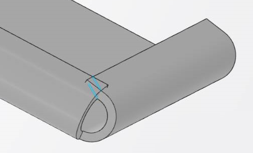
Cause: Null Radius Bend

The thin solid mesher cannot generate the mesh for a part that has an inner bend with a sharp edge.
Solution: In a sheet metal design app, edit the geometry so that the part does not include a null radius bend.
Cause: Twisted Faces in Geometry
When a geometric face is severely twisted, the mesher can either fail to mesh the part or create a mesh with some elements that are of very poor quality.
Solution: Remesh the part that has twisted geometry so that it uses a finer mesh.
Cause: Overlapping Faces

The modeled part or assembly has geometry faces that either intersect or overlap. In the example above, the modeled part does not represent a possible physical part and cannot be manufactured.
Solution: In a sheet metal design app, use the Check Overlapping tool to detect intersections or overlaps in your design. Then remove these areas from the part or assembly.
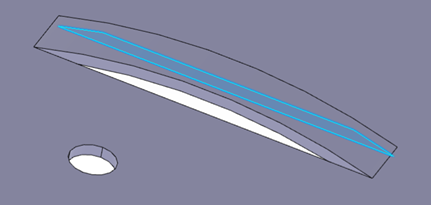
Cause: Knife Edge

The modeled part or assembly has geometry with small triangular (side) faces. These small triangular regions can cause the mesh generation to fail because the mesher cannot find the top and bottom faces.
Solution: In a sheet metal design app, edit the part or assembly to avoid knife edges.
Cause: Stamp Feature (with Sharp Edges)

The modeled part or assembly has a stamp feature with sharp edges. These sharp edges can cause the mesh generation to fail because the mesher cannot find the top and bottom faces to create the thin solid mesh properly.
Solution: In a sheet mesh design app, use the with fillet option to recreate the stamp feature without sharp edges.
