Using Contact Detection | |||||
|
| ||||
-
From the
Interactions section of the
action bar,
click
Contact Detection
 .
.
-
Choose the
Search domain:
- Whole Model: Search all components in the assembly for contacting surfaces. This is the default if you do not select any geometry.
- Select candidate geometry supports by clicking individual components in the model. Contact features are considered only between the selected components. If you select a single component, contact features are considered only between surfaces on the selected component and any other contacting surfaces in the model.
- Select mesh parts from the tree or from the view. When mesh parts are selected along with Detect interactions on: Mesh, surface-based contacts are created only between the selected mesh parts.
- Optional: Change the default Search tolerance. This value defines the maximum separation distance between surfaces that can be considered to be in contact.
-
Choose an option for
Detect interactions on to determine the type
of supports to search for contact.
Option Description Geometry Creates contact pairs from geometry supports. Mesh Creates surface contact pairs from native and orphan mesh parts. Groups are generated within the mesh parts, and these groups are selected as supports in surface-based contact pairs.
Shell thickness and offset can affect the results of the contact search; see Shell Thickness and Offset in Contact Detection.
- Optional:
If you selected
Mesh in Step 4, you can specify an angle by
which to extend the meshed faces. The default
Extend by angle is 10 degrees.
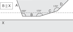
The following example shows a potential contact case, including the effects of the Extend by angle option.

Mesh surfaces B and X (represented in two dimensions) are parallel, and lie within the contact detection distance (Search tolerance) represented by the dashed line. The adjacent surfaces A, C, and D are attached to B at the given angles. With no other options, a surface contact pair is created for B and X. Using the default Extend by angle (10º), surface B is extended to include surfaces C and D; the angle is measured at each surface change, not as a total angle from the original surface. Surface D is included, even though it lies beyond the search tolerance, because it is now considered to be an extension of surface B.
- Optional:
Select an Interaction property to be assigned to all
contact features when created. This list lets you choose from any contact
interaction properties you have already defined.
If you do not choose a specific property, the (Default penalty contact) is applied—this provides a basic type of contact that equates to the following Abaqus keyword:
*SURFACE BEHAVIOR, PENALTY=LINEAR
, 0., 1.
Note that this (Default penalty contact) is different from the behavior defined by an "empty" contact property (with no options selected).
- Optional:
Select Tie surfaces together to create contact features
that tie the surfaces together; no relative motion between the surfaces occurs
at contacting interfaces during the simulation.
Note: The Tie surfaces together option is not available in thermal simulation steps.
-
Click
Find Surface Pairs.
A separate dialog box shows the surface pair detection progress. When completed, a table displays contact features created for surfaces that meet the detection requirements. You can edit these contact features as necessary:
-
Right-click on any row in the table to
Locate,
Edit, or
Remove that contact feature. You can also
choose
Invert Selection to select the other
contact features in the table.
Note: If you select Edit from the context menu, the Surface-Based Contact dialog box opens to let you enter parameters for all selected contact features. These options are described in Defining Surface-Based Contact in Implicit Steps.
- Select multiple rows in the table ([Ctrl]+[Click] or [Shift]+[Click]) and then choose Edit, Merge, or Remove for those features. Again you can choose Invert Selection to select the other contact features in the table.
-
Right-click on any row in the table to
Locate,
Edit, or
Remove that contact feature. You can also
choose
Invert Selection to select the other
contact features in the table.
- Optional: You can change the search domain or tolerance and click Find Surface Pairs again to change the search criteria. Any new surface pairs found are marked by an asterisk (*) in the table.
- Click OK.