About Rendering Settings | ||||
|
| |||
When you first display the results of your simulation, the app displays the finite element representation of the products and parts and hides the geometry associated with those products and parts. Any products and parts that do not participate in the simulation are also hidden by default.
You can reveal the geometry of any parts or products in your simulation by selecting them from the tree in the Rendering Settings dialog box and changing the rendering behavior using the available options. The tree displays a hierarchical view of all the geometry in your simulation. You can also filter what appears in the tree if you want to search for products or parts whose names match the search string you provide. Highlight the part or parts whose rendering behavior you want to change.
Whole Plot Options
You can adjust the transparency of the whole model and apply the following material styles to the part: Default, Metal, Plastic, or Rubber. The material style is used for rendering all surfaces (shaded, contour, isocontour) from simulation results data.
You can also adjust the transparency of any position along the contour gradient. You can
add or delete markers on the sliding scale, drag them to new locations, and establish
transparency values for each marker. 
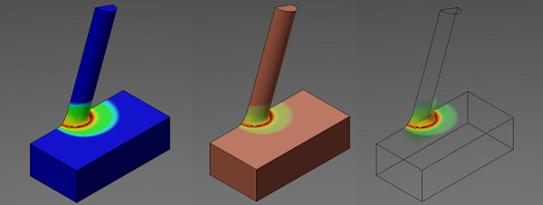
Finally, when using variable contour transparency, you can choose whether to display or
hide the model material behind the contour. The model below of a projectile and plate
displays von Mises stresses at the point of contact. In the image on the left, variable
contour transparency is off, and the model is hidden. Only the contours display. In the
middle image, variable contour transparency is set to display the clay model. The
transparency is set at 100% for a position 30% along the contour. The blue values are now
transparent, and the clay model shows through the transparent areas. In the image on the
right, the variable transparency is set to the same values as in the middle image. However,
the model material is hidden.
Part Options
You can adjust the rendering of the associated geometry that you display and the simulation results. The rendering controls differ for the two types of data:
- For model data, you can display or hide the geometry; when the geometry is displayed, you can adjust its material transparency. You can also apply the rendering from the material assigned to the part directly to the mesh.
- For results data, you can adjust the transparency and hide the display of edges. You can also display the model using the rendering material from the model rather than the results material.