Define the Static Step to Remove the Build Tray
-
From the Procedures section of the action bar, click Static Step
 . .
-
Name the static step Static
Step_Remove_BuildTray.
-
Enter a step time, initial time increment, and maximum time increment of
1s.
-
Click OK.
-
From the Structural Restraints & Loads section
of the Assistant, click Clamp
 . .
-
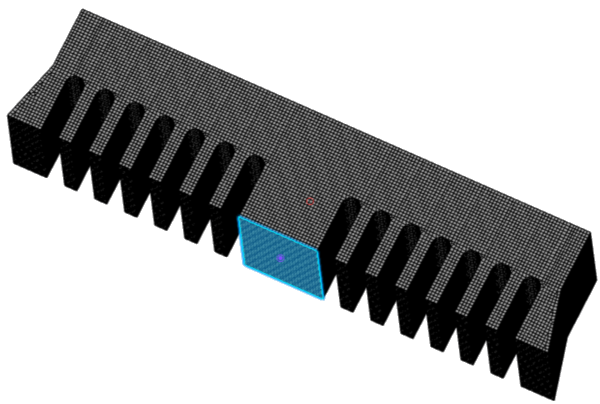
Select the two faces of the bridge parallel to the global xz plane.
A clamp is added to these faces to prevent free body motion since the part
was constrained by the build tray and supports that are being
removed.
The Support field indicates that two faces
are selected. 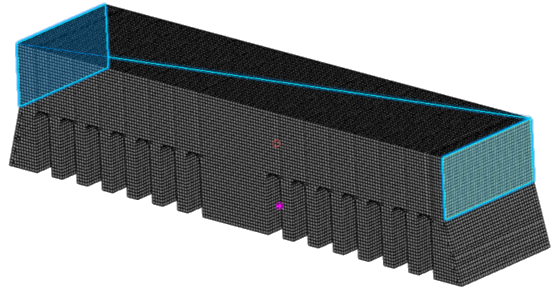
-
Click OK.
-
From the Interactions section of the action bar, click Model Change Manager
 . .
-
Click Add
 . .
The Model Change dialog box
opens.
-
From the Support options, select Mesh
part
 as the
selection method. as the
selection method.
-
From the selection tree, select Sweep_3D_buildtray, and click
OK.
-
From the Model Change dialog box, click
OK.
The build tray is shown in the Model Change Manager
as a component that you can change in the simulation model. It is active in
all steps.
-
Clear Sweep_3D_buildtray from the Static
Step_Remove_Buildtray column.
By clearing the check box, you are deactivating the build tray for the
selected step and any subsequent steps.
-
Click OK.
-
From the tree, right-click , and click Remove Prescribed Temperature.2 in
Static Step_Remove_Buildtray.
Define the Static Step to Remove the Supports
-
From the Procedure section of the action bar, click Static Step
.
-
Name the static step Static
Step_Remove_Support.
-
Enter a step time, initial time increment, and maximum time increment of
1s.
-
Click OK.
-
From the Interactions section of the action bar, click Model Change Manager
.
-
Click Add
.
The Model Change dialog box
opens.
-
From the tree, select as Supports, and click
OK.
-
Clear Supports from the Static
Step_Remove_Support column.
-
Click OK.
-
From the Structural Restraints & Loads section
of the Assistant, click Clamp
.
-
Select the bottom surface of the center pillar of the bridge part.
-
Click OK.
A new clamp is created to replace the one previously defined to control
the location of the bridge part. You will remove the previously defined
clamp and other restraints in the next steps.
-
From the tree, right-click , and click Remove Clamp.2 in Static
Step_Remove_Support.
The clamp is removed from the Static
Step_Remove_Support.
-
From the tree, right-click , and click Remove Fixed_Displacement_X in Static
Step_Remove_Support.
-
Repeat Step 14 to remove Fixed_Displacement_Y and
Fixed_Displacement_Z.
The fixed displacements are removed from the Static
Step_Remove_Support.
-
From the Standard section of the action bar, click Feature Manager
 , and
select Scenario , and
select Scenario
 . .
The scenario view of the Feature Manager is shown below.
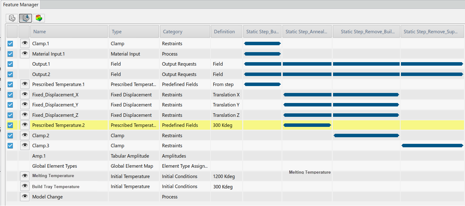
The Feature Manager displays the contributing parts, scenario features, and results
plots. You can edit, delete, locate, and hide or show features and
plots. Note:
The row highlighted in yellow indicates an amplitude was
applied on an entry using nonstandard units. You must take care with
units when using amplitudes. The 3DEXPERIENCE platform converts units before performing other operations. This can
result in unintended values when the amplitude is applied. In this
case, we used Kelvin throughout the example and will use the same
units to solve the simulation; therefore, there will be no issue and
we can ignore this warning.
|