-
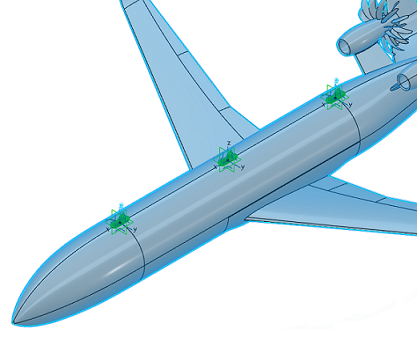
Define a placement candidate at the front of the passenger cabin.
-
From the Placement Candidate section of the Assistant, click Placement Candidate
 . .
-
Name the first placement candidate Front
Candidate.
-
From the Placement method options, click
Two Axis Systems
 to
define a placement candidate using an axis system from the platform and
an axis system from the antenna. to
define a placement candidate using an axis system from the platform and
an axis system from the antenna.
-
From the Antenna options, verify that the app selected your antenna.
When there is only one antenna in the simulation, the app selects the antenna automatically.
-
From the Antenna axis options, select the
antenna axis system corresponding to its anchor point.
-
In the 3D area, select the aircraft's frontmost axis system.
A yellow antenna glyph appears at the front of the passenger cabin to denote the
placement candidate.
-
Verify the position and orientation of the antenna geometry.
-
Click OK.
The dialog closes and the placement candidate glyph becomes
green. 
-
Similarly, define two additional placement candidates named Middle
Candidate and Rear Candidate using axis
systems at the middle and rear of the passenger cabin.
Two additional green antenna glyphs appear on the passenger
cabin.
|