Add the DOE Adapter
-
Scroll the action bar to the right to display the process
adapters in the secondary area.
-
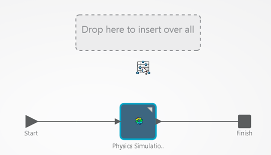
From the Flow section of the action bar, click DOE
 and
move the cursor over the process flow diagram. and
move the cursor over the process flow diagram.
-
Drop the adapter in the Drop here to insert over all
box that appears.

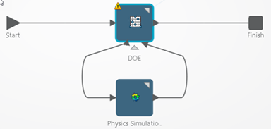
The DOE adapter appears over the physics simulation in the process
flow diagram. The diagram describes a simulation process. Each blue box
represents a simulation activity inside the simulation process. For example,
DOE in the figure below represents a simulation
activity.

Configure the DOE Adapter
-
Double-click the DOE adapter to open the editor.
-
From the
General tab, select
Latin Hypercube as the
DOE Technique.
Your choice of DOE technique depends on several factors, including:
- Parameters you want to study.
- Number of experiments or trials you can afford to run.
- Output quantities of interest.
- Overall goal of the study.
The
DOE Editor displays the advantages and
disadvantages of each DOE technique, and more details are provided in the
Process Composer
guide. The Latin Hypercube technique is suitable for this simple example. Latin
Hypercube allows many points and combinations to be studied, as long as the
number of design points is greater than the number of input parameters.
-
Enter
4 as the
Number of points.
The DOE adapter will run four simulations while varying
the dimensions of the beam. The combination of data points that will be studied
is a function of the selected DOE technique.
-
From the
Factors tab, select all three input
parameters to be varied.
-
Enter the lower and upper limits for the range of each input
parameter as shown in the table below:
| Parameter
|
Lower
|
Upper
|
Relation
|
| Height
|
-50
|
50
|
%
|
| Length
|
0
|
50
|
%
|
| Width
|
-50
|
50
|
%
|
The values that you enter are a percentage of the baseline—the original dimensions of the
beam geometry. For example, the original width was 30 mm, and the DOE
will explore widths between 15 and 45 mm.
-
From the
Design Matrix tab, observe the combination
of the geometry dimensions to be tested during the four runs.
The DOE uses a random seed to generate the values in the
design matrix. As a result, the values will change each time you configure the
DOE. To produce repeatable results, you can select a fixed seed from the
General tab.
-
From the
Responses tab, select all three output
parameters as DOE responses to be monitored.
-
Click OK.
-
Save your work.
|
 and
move the cursor over the process flow diagram.

