Mesh the CPU Enclosure
-
From the
Standard section of the
action bar,
click
Mesh
 .
The model opens in Mesh Creation.
 -
From the
Mesh section of the
action bar,
click
Hex-Dominant Mesh
 .
.
-
Enter a maximum size of 6 mm and a minimum size of
0.4 mm.
This represents the global element edge sizes.
-
Enter a minimum angle between faces of
30deg.
This represents the smallest angle between geometric faces that will result in an edge between element faces.
- Select Add boundary layers.
- Enter a first layer thickness of 0.1 mm, and set the number of layers to 3.
-
Click
Mesh, and then click
OK.
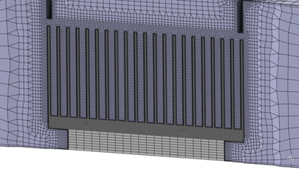
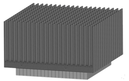
Tip: From the tree, right-click Finite element model > Nodes and Elements and click Hide/Show to show the mesh. The hex-dominant mesh on the CPU enclosure is shown below. This represents the fluid mesh.

- Optional:
View the mesh along different cutting planes by doing the following.
-
From the Display section of the action bar, click Sectioning
 .
.
- Clear the Exact mesh cut selection.
-
Drag the cutting plane in the 3D area to change the location of the cut.
The default cutting plane is the X-axis.
- Select Y-axis and Z-axis to view the mesh along other cutting planes.
- Click Close.
-
From the Display section of the action bar, click Sectioning
