-
From the Setup section of the action bar, click Finite Element Model
 . .
-
From the Model options, select
Create to create a FEM.
-
Name it FEM_ConHT, and click
OK.
FEM_ConHT A.1 appears in the tree.
-
From the View section of the action bar, click Fit All In
 . .
The app enlarges or shrinks the model to fit in the 3D area.
-
From the standard area of the action bar, click Model
 . .
The model opens in Fluid Model Creation.
-
From the Setup section of the action bar, click Fluid Domain
 . .
-
Name the fluid domain Enclosure_1.
-
From the Definition field, select Extract
from part boundaries.
-
Select the structural parts that contain the fluid and are surrounded by the
fluid flow.
-
Click
 on the Parts container. on the Parts container.
-
From the 3D area, click and drag a rectangle around
the entire model to select the heat sink, chip, and enclosure.
The Support field indicates that six
mechanical features are selected. 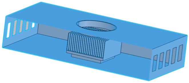
-
Select Allow boundary layers to be added to
enable the creation of boundary layers along the part boundary.
-
Click OK.
-
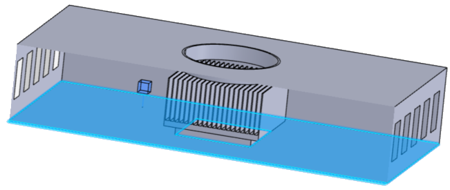
Specify the regions where the fluid flows.
-
Click on the Regions
container.
-
Select the inside bottom surface, which is next to the chip.
A glyph  appears, indicating that the fluid is located
outside the enclosure.
-
Click Flip direction to specify that the fluid
is passing through the enclosure rather than around it.
The glyph moves to the interior of the enclosure.
-
Click OK.
-
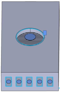
Indicate the openings of the fluid domain. There are 11 openings to define, all
of them on the CPU surface enclosure. One opening is the round vent above the
heat sink, and the other 10 openings are the small rectangular vents on the ends
of the enclosure.
-
Click on the Openings
container.
-
Define the circular opening by selecting the two inner edges of the
round vent.
A circular disc glyph shows the location of the
opening.
-
Click OK.
-
Define a rectangular vent opening by selecting each of the four edges
of the small rectangular vents, and click
OK.
-
Similarly, repeat Step d to define the other nine openings.
-
Click OK.
|
 from the context toolbar. A circular disc glyph shows the location of the opening.