-
In the top bar, search for Mat*, and select
EXAMPLE-Mat-Alloy Steel.
The asterisk is a wildcard symbol.
-
Right-click the material in the search results, and click
Open.
The material opens in Material Definition. It contains both appearance and simulation domain properties.
-
Click EXAMPLE-Driveshaft-Subassembly A in the tabs at
the top of the work area to return to the driveshaft assembly.
The 3DEXPERIENCE platform returns to Model Assembly Design.
-
From the tree, double-click Global FEM.
The model opens in Structural Model Creation.
-
From the Setup section of the action bar, click Pick Material
 . .
-
Click Material Editor in the tabs at the top of the work area.
The Material Definition app opens and displays the materials loaded in the current session. The
pointer appears as an eyedropper, indicating that you are picking a
material. Note:
If you do not see the materials list, press
F3 to display the tree.
-
From the tree, select EXAMPLE-Mat-Alloy Steel.
The 3DEXPERIENCE platform returns to Structural Model Creation and the pointer includes  , indicating that
you are applying the selected material. -
Complete the following steps for each part in the driveshaft assembly:
-
From the tree, click the part name.
-
From the context toolbar, click
 . .
-
After you apply the material to the last part, reopen the context toolbar and click
 . .
-
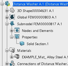
Expand the parts in the tree, and verify that each part now includes the following:
- A Materials node that contains the material
definition
- A Solid Section without warnings or errors
 Note:
If the materials are there but you see an
exclamation
point symbol on the solid section icon, click
Update All
 in the
standard area of the action bar. The exclamation point indicates that the material change for the solid
section did not register. in the
standard area of the action bar. The exclamation point indicates that the material change for the solid
section did not register.
-
Save your work.
|