-
From the tree, double-click EXAMPLE-Driveshaft-Subassembly A.
The 3DEXPERIENCE platform returns to Model Assembly Design.
-
From the Automated FEM section of the action bar, click Automated FEM
 .
.
The Automated FEM dialog box appears, indicating
the available methods for generating a FEM representation.
-
From the General Purpose methods, click User
Driven.
The Automated FEM: User Driven dialog box appears
and displays the structure of the model. The plane is hidden because it is an
abstraction shape, not a geometry that you can mesh.
-
Select the rows for both the hollow shaft and the support shaft.
-
Right-click the Procedure cell for one of the selected
rows.
-
From the context menu, click .
You can apply a submodel procedure only to the parts that extend through the submodel
boundaries. The submodel meshing procedure ensures continuity from the coarse
mesh of the global FEM to the finer mesh of the submodel FEM. In this example,
the hollow shaft and supportive shaft cross the plane that defines the submodel.
Therefore, you must define a submodel procedure for both of these parts before
meshing them.
-
Edit inputs for the submodel procedure.
-
Select the rows for both the hollow shaft and the support shaft, and
right-click the Procedure cell for one of the
selected rows.
-
From the context menu, click Edit Inputs.
-
For the Cutting surface, use the tree to expand , and select Plane.1.
-
Enter 5mm as the Mesh
size.
-
From the Element order options, select
Linear.
-
Enter 0.1mm as the Sag
value.
-
Select Create solid section.
You must create a solid section before you can apply a material
definition to the parts.
-
Click OK.
-
In the Automated FEM dialog box, select the rows for the
remaining parts in the submodel (that is, the sprocket, bearing, distance
washer, and bearing stopper).
These parts all belong to the submodel exclusively. They do not cross the
submodel boundaries.
-
Similar to the procedure you defined for the hollow shaft and the support
shaft, apply a procedure to these parts using a tetrahedron mesh, a 5-mm mesh
size, and a 0.1-mm sag to create the solid sections.
-
Click Run.
The Finite Element Model dialog box appears, showing the
solver's progress as it creates the FEM representations for the
parts.
-
When the process completes, click Yes to refresh the
session.
The
Automated FEM dialog box displays the results, and the
app updates the
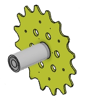
3D area to show only the submodel. For visual clarity, the image below shows the
submodel without the meshes.

-
You may ignore bad elements in these meshes.
Bad elements indicate that a tetrahedron mesh element's shape is skewed or
stretched. Addressing bad elements is not within the scope of this
example.
-
Right-click the new FEM representation in the tree, and rename it Submodel FEM.
The 3D area
displays the submodel with all of its parts meshed. The app
meshed each part individually and collected the meshes to create the submodel
FEM.