Create an Abstraction Shape
-
Right-click EXAMPLE-Driveshaft-Subassembly A, and select .
The New Content panel appears.
-
Expand Simulation Model, and select Abstraction
Shape.
The new abstraction shape appears in the tree. 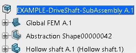 -
Right-click the abstraction shape, click Properties, and
rename it Abstraction Plane.
Confirm that you are using Model Assembly Design. You cannot create the abstraction plane otherwise.
Create and Position the Plane
-
From the tree, expand Abstraction Plane, and double-click
PartBody.
Note:
If you previously used other 3DEXPERIENCE geometry editing apps
during your session, the part might open in one of those apps instead. To continue the
example, you can select the Compass and search for the Simulation Model Preparation
app.
The abstraction shape opens in Simulation Model Preparation.
-
From the Create section of the action bar,
click Plane.
-
From the Type options, select Offset from
plane.
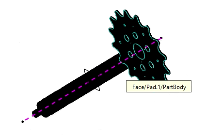
-
In the 3D area, select
the inner face of the sprocket as the Reference, as shown
below.
-
Enter 300mm as the Offset.
-
Click Preview.
The plane appears along the driveshaft to the left of the sprocket, as shown
below. 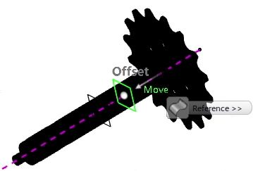 If the plane appears to the right of the sprocket, click  in
the Plane dialog box to reverse the offset direction. in
the Plane dialog box to reverse the offset direction.
-
Click OK.
|