-
Ensure that the analysis context is set to Submodel
Analysis.
-
From the Boundary Conditions section of the action bar, click Submodel Displacement
 . .
This feature transfers the displacement degrees of freedom from the global
model to the submodel along their shared boundaries, such that the submodel
motion follows that of the global model.
-
Select the cut faces at the ends of the hollow shaft and the supportive
shaft.
-
From the tree, expand the shaft parts.
-
Select the submodel FEMs (that is, the second FEM in each part).
-
Hide the meshes.
-
In the 3D area, select the cut faces of the shaft parts.
-
For the Global Step, select Static
Step.1.
-
Click OK.
-
Change the analysis context to Global
Analysis.
-
From the Loads section of the action bar, click Force
 . .
-
Select one of the valleys between the gear teeth on the sprocket, and enter
-1000N in the global Z-direction.
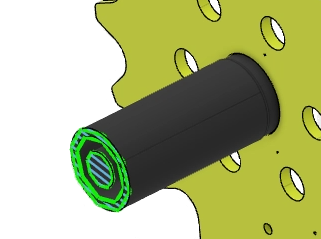
The app applies the force, as shown below. The force transfers from the sprocket
teeth to the driveshaft as a pure rotational force. 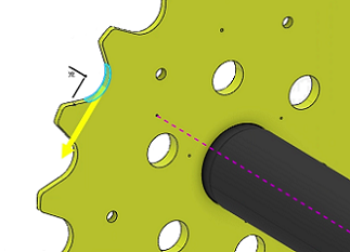 -
From the Boundary Conditions section of the action bar, click Fixed Displacement
 . .
-
In the 3D area, select the end of the support shaft that is furthest from the
sprocket.
-
Select
the X, Y, and Z rotational and translation degrees of
freedom, and click OK.
The restraint is shown below. 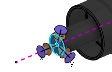 -
Change the analysis context to Submodel
Analysis.
-
Similarly, create a restraint on the end of the support shaft that is closest
to the sprocket.
The
displacement restraints for the submodel use only one end of the shaft.
The
submodel displacement load supports the shaft at the boundary between the global
model and the submodel.
|
 .
.