-
From the Boundaries section of the Assistant, click Velocity Inlet
 . .
-
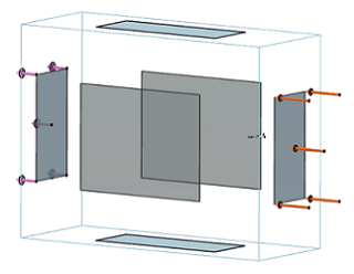
Select the outer side of the bounding box (that is, the blue rectangular glyph)
that is in front of the drone's nose as the support.
A set of orange arrows appears in the 3D area. These arrows, which represent the direction of airflow, point toward the
drone's nose.
-
Enter 22.352m_s in the Velocity
field, and click OK.
-
From the Boundaries section of the Assistant, click Pressure Outlet
 . .
-
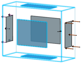
Select the outer side of the bounding box that is behind the drone's tail as
the support, and click OK.
0 N/m2 static gauge pressure is representative of atmospheric
pressure, which is a typical flight condition for this drone's missions.
A second set of arrows, which represent the pressure, appears in the 3D area, as shown below. -
From the Boundaries section of the Assistant, click Symmetry
 . .
-
Select the side of the bounding box that divides the drone into symmetrical
halves, and click OK.
A semitransparent cuboid, which represents the symmetry condition,
appears on the selected face of the bounding box.
-
From the Boundaries section of the Assistant, click Wall
 . .
-
Select the top, bottom, and side of the bounding box as the support, as shown
below.
-
From the Wall type options, select
Slip.
A slip wall type prevents fluid from sticking to the selected surface. Since the drone is
in an open environment, a boundary layer at any of the bounding box's surfaces
is undesirable.
|