-
From the Assistant, click Model.
The Finite Element Model dialog box
appears.
-
From the Model options, select
Create to create a finite element model (FEM).
-
Name it Airflow Mesh, and click
OK.
Airflow Mesh A.1 appears in the tree.
-
From the Model section of the Assistant, click Model Setup
 . .
-
Select Include external flow.
A bounding box appears around the drone. 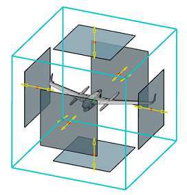 -
Apply the material definition for air to the fluid section associated with the
fluid domain.
-
Click
 to open the Material Palette. to open the Material Palette.
-
From the Material Palette, search for
MynameEXAMPLE-Air.
-
Select MynameEXAMPLE-Air, and
click OK.
The app applies the material definition to the fluid section and closes the
Material Palette.
-
Expand the Fluid domain bounding parts section, and
confirm that all five parts are selected.
-
Resize the bounding box to enclose a symmetric half of the drone.
-
Expand the Bounding box section.
-
Enter the following coordinates for the Minimum
and Maximum values of X,
Y, and Z:
| Axis |
Minimum |
Maximum |
| X |
-30000mm |
10000mm |
| Y |
-15000mm |
0mm |
| Z |
-15000mm |
15000mm |
These coordinates create a bounding box that divides the drone into two
symmetrical parts. 
-
Confirm that all bounding box faces specify No boundary
layers
 . .
Boundary layers on the bounding box faces are useful when these faces
represent a solid surface, like a road or the walls of a wind tunnel
simulator. In this example, you simulate the drone flying in normal
operating conditions with no solid surfaces within close proximity to
the drone.
-
Specify the region that contains the fluid.
-
Expand the Regions section.
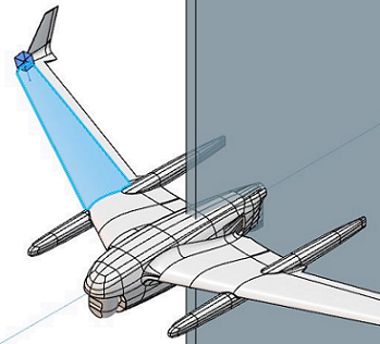
-
Select any surface of the drone that is also inside the bounding
box.
A glyph of a blue cube with a stem  appears on that surface.
-
If required, click Flip direction
 to immerse the cubical portion of the glyph in the fluid
volume. to immerse the cubical portion of the glyph in the fluid
volume.
-
Click OK.
|