Customize the Mesh
-
Define a coarse mesh for the entire fluid domain.
-
From the tree, expand Nodes and Elements, and double-click
Hex Mesh.1.
-
Enter 500mm as the Maximum size,
and enter 20mm as the Minimum
size.
-
Enter 30deg as the Minimum angle between
faces.
-
Select Add boundary layers to specify the distribution of
elements at the surface of the fluid domain.
-
Enter 4mm as the First layer
thickness, and enter 3 as the Number
of layers.
-
Expand the Options section, and clear all
selections.
-
Refine the mesh along the surface of the drone.
-
Expand the Local Specifications section, and click
Local Mesh Size on Face and Edge
 . .
-
From the context toolbar, click Select faces by propagation
 . .
-
Select any surface of the drone.
A second context toolbar appears.
-
Enter 180deg in the context toolbar, and click Propagate.
You have selected the entire surface of the drone for surface mesh
refinement. Refining the surface mesh improves the accuracy of your results at the
surface. This is especially useful when your model includes curvy geometries like
the surfaces of this drone. 
-
In the Local Mesh Size on Geometry dialog box, enter
10mm as the Size, and click
OK.
-
Refine a portion of the overall mesh by creating a Cartesian box around the
drone.
-
From the Local Specifications section, click
Local Mesh Size in Cartesian Box
 . .
-
Enter the following values for the Origin (X,Y,Z) and
Size (X,Y,Z) of the Cartesian box:
|
X |
Y |
Z |
| Origin |
-4000 |
-3000 |
-1000 |
| Size |
5000 |
3000 |
1800 |
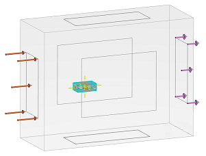
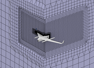
These Cartesian values create a smaller box within the bounding box. The
smaller box serves to bound the refined section of the mesh. Like the bounding box,
it divides the drone into two symmetrical parts. 
-
In the Local Mesh Size in Cartesian Box dialog box, enter
100mm as the Mesh size, and click
OK.
-
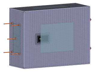
Click Mesh to start the meshing process.
Note:
Clicking Mesh starts the meshing process immediately;
clicking OK saves the dialog box settings and closes the dialog
box without meshing.
The PLM Update... window appears and displays the
meshing progress. This window closes automatically when the app
completes the meshing process.  -
Click OK.
-
Save your work.
Visualize the Mesh
-
Hide the bounding box.
-
From the tree, expand .
-
Right-click Bounding Box.1, and select
Hide/Show
 . .
-
Display a cross-section of the mesh.
-
From the Display section of the Assistant, click Sectioning
 . .
-
From the Plane options, select
X-axis, Y-axis, or
Z-axis to specify the cutting plane.
The cutting plane is the plane normal to the selected axis.
-
If desired, click Reverse to display the mesh on the other
side of the cutting plane.
-
Clear Exact mesh cut to show whole elements on the cutting
plane.
-
Move the cutting plane in the direction of the selected axis by dragging the
cutting section with your pointer.
-
Inspect the density of the mesh in critical areas of the model.
-
From the Display section of the action bar, click Visualization Management
 . .
-
From the Shape options, select Hide
 to hide the drone. to hide the drone.
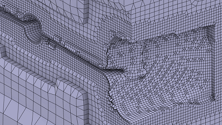
The mesh appears fine at the surface of the drone, and it coarsens outside
of the Cartesian box that you defined earlier. You can verify the number of boundary
layer elements that you specified when creating the mesh. 
-
From the Shape options, select Show
 . .
-
Close both the Visualization Management and
Sectioning dialog boxes.
|
 .
.
 .
.

 .
.


