-
From the Assistant, click Model.
The Finite Element Model dialog box appears.
-
From the Model options, select Create to
create a FEM.
-
Name it
DuctFlow_Mesh,
and click OK.
DuctFlow_Mesh A.1 appears in the tree.
-
From the Model section of the Assistant, click Model Setup
 . .
-
Apply the material definition for air to the fluid section associated with the fluid
domain.
-
Click
 to open the Material Palette. to open the Material Palette.
-
From the Material Palette, search for
MynameEXAMPLE-Air.
-
Select MynameEXAMPLE-Air, and click
OK.
The app
applies the material definition to the fluid section and closes the Material Palette.
-
Expand the Fluid domain bounding parts section, and confirm that
the duct part is selected.
-
Select the region that contacts the fluid.
-
Expand the Regions section.
-
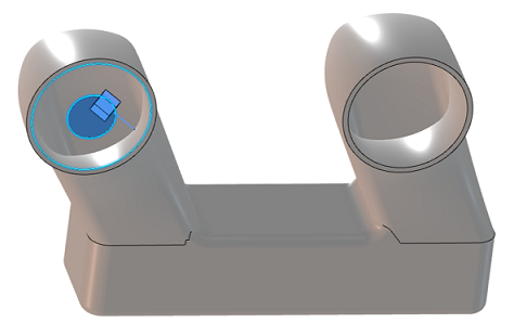
Select a surface inside the duct.
A glyph of a blue cube with a stem  appears
on that surface.
-
Select or clear Flip direction
 to ensure
that the cubical portion of the glyph is immersed in what would be the fluid
volume. to ensure
that the cubical portion of the glyph is immersed in what would be the fluid
volume.
-
Define the openings that allow fluid to flow through the duct.
-
Click
 in the Openings section. in the Openings section.
-
From the context toolbar, select Edge Propagation
 . .
-
Select an edge on the inner side of the duct opening on the left.
-
Enter 30deg in the pop-up window, and click
Propagate.
The app
highlights all of the edges that comprise the duct's opening.
-
Define the second duct opening in the same manner.
-
Expand the Mesh section, and accept the default mesh density for
the fluid interior and fluid walls.
You customize these settings later in this example.
-
Click OK.
Three new items appear in the tree:
- Physical Environment.1 appears underneath the
Abstractions node.
- Fluid Section.1 appears underneath the
Properties node.
- Hex Mesh.1 appears under the Nodes and
Elements node.
|