-
From the Setup section of the action bar, click Finite Element Model
 . .
-
In the Finite Element Model dialog box, select the
predefined FEM named
myNameBucket weld study
A.1, and click OK.
-
From the tree, review the model's structure.
The welds are separate products (and are, in fact, bundles of welds created in the Weld Design app). In addition, some parts of the FEM are represented by abstraction
shapes. An abstraction shape is a container into which you can copy the original
model to allow complete editing without impacting the source content.
-
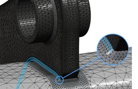
Examine the mesh. You can review the mesh settings of one of the parts
connected by the weld to see where the face capture tool is used. This tool
configures the mesh so that the weld and the connected part share nodes where
they are in contact.
-
From the tree, expand .
-
Right-click the first meshed part named Right
Mount, and click Reframe
On.
-
Expand , and click Face Capture.3.
The app highlights the part of the mesh defined by the specification. You can
zoom in for a closer look.
-
From the tree, double-click Face Capture.3.
-
Select Visualize captured mesh to highlight the
area of the mesh between the fillet and the bracket with nodal
condensation (that is, shared nodes).

The shared nodes appropriately represent the material bond formed during the welding
operation.
|