-
From the Procedures section of the action bar, click Static Perturbation Step
 . .
-
Accept all the default settings for the static perturbation step, and click
OK.
-
From the Boundary Conditions section of the action bar, click Hinge
 . .
-
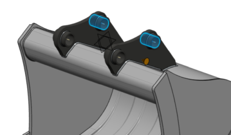
Define a hinge restraint on the first pair of bearing faces, as shown below.

-
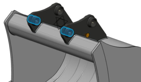
Similarly, define another hinge restraint on the second pair of bearing faces, as shown
below.

-
Restrain the sideways motion of the bucket.
-
From the Boundary Conditions section of the action bar, click Fixed Displacement
 . .
-
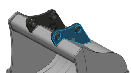
Select the face shown below as the
Support.

-
From the Translation options, select
X.
-
Create the first load set.
-
From the Loads section of the action bar, click Load Set
 , and
name it Left. , and
name it Left.
The app creates the load set and displays it in the context selector.
-
From the Loads section of the action bar, click Force
 . .
-
From the Support options, select
Connection
 . .
-
Click the coupling named left.
-
Enter a unit force of -1 N in the
Force Y field. Leave the other force
components set to zero.
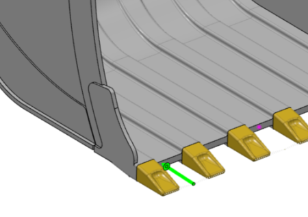
The app displays a green arrow, as shown below, that indicates the location and
direction of the force.  -
Similarly, create the remaining load sets.
-
Create a load set named Mid with a load
identical to that used in the previous load step, but use the coupling
mid as the support.
-
Create another load set named Right with a load
identical to that used in the other load steps, using the coupling
right as the support.
-
Use the context selector to switch from the load set back to the static perturbation step.
-
Create the load cases.
-
From the Loads section of the action bar, click Load Case
 . .
-
From the Load Case editor, click Use
load sets.
-
In the Add Load Sets dialog box, select
Left, specify a scale factor of
120,000, and click
OK.
-
Similarly, create two load cases for the load sets
Mid and Right.
|