Customize the Mesh
-
From the tree, expand Nodes and Elements, and double-click Hex
Mesh.1.
-
Enter 20mm as the Maximum size, and
enter 1.75mm as the Minimum size.
-
Select Add boundary layers to specify the distribution of
elements at the surface of the fluid domain.
-
Enter 0.05mm as the First layer
thickness, and enter 4 as the Number of
layers.
-
Expand the Options section, and clear all selections.
-
Click Mesh to start the meshing process.
Note:
Clicking Mesh starts the meshing process immediately;
clicking OK saves the dialog box settings and closes the dialog
box without meshing.
The PLM Update... window appears and displays the
meshing progress. This window closes automatically when the app
completes the meshing process.  -
Click OK.
-
Save your work.
Inspect the Mesh
-
From the Mesh section of the Assistant, select Quality Analysis
 . .
-
Select the Connectivity tab.
The quality report shows how many meshes, nodes, and elements were generated in the
finite element model. It also displays the composition of the mesh in terms of element
type. The coolant mesh has approximately three million elements.
-
Display a cross-section of the mesh.
-
From the Display section of the Assistant, click Sectioning
 . .
-
From the Plane options, select
X-axis, Y-axis, or
Z-axis to specify the cutting plane.
The cutting plane is the plane normal to the selected axis.
-
If desired, click Reverse to display the mesh on the other
side of the cutting plane.
-
Clear Exact mesh cut to show whole elements on the cutting
plane.
-
Move the cutting plane in the direction of the selected axis by dragging the
cutting section with your pointer.
-
Inspect the density of the mesh in critical areas of the model.
-
From the Display section of the action bar, click Visualization Management
 . .
-
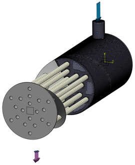
From the Shape options, select Hide
 to hide the heat exchanger. to hide the heat exchanger.
-
Similarly, hide the scenario features.

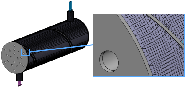
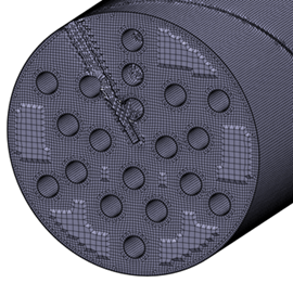
The mesh appears fine at the surfaces of the heat exchanger parts (for example,
the tubes and the baffle), and it coarsens as you move away from those surfaces.
You can verify the number of boundary layer elements that you specified when
creating the mesh. Based on your inspection, you could refine or coarsen the mesh
to improve the results or performance, respectively.
-
Display the shape and scenario features again.
-
Close both the Visualization Management and
Sectioning dialog boxes.
|


