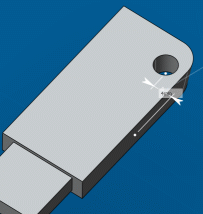
-
Select the faces, edges, and vertices you want to constrain.
In this example, two faces.
For more information, see Available Constraints by Entity. -
Select the type of constraint you want to apply.
In this example, Distance is used to create a dimensional constraint.
The context toolbar shows only those constraints that can be applied to the current selection.
 By default, 3D dimensions (distance, angle, radius) are driving dimensions  . . - To change the dimension type to driven, click Driven Dimension
 . . - To orient a constraint and ensure that the geometry moves in the desired direction, click the appropriate option in the context toolbar.
Orienting a constraint determines which side moves. An arrow shows the side that changes. Notes:
- If multiple constraints are added, constraints are solved as a system and the best possible solution determined. In this case, you may not get the expected result.
- If one side is an external app feature, the constraint is always oriented from the external feature to the natural shape.
- Optional:
Drag to move and correctly position the graphical representation of the
constraint.
- To re-route constraints and change the anchor point, select the constraint and do one of the following:
Note:
In most cases, re-routing does not modify existing geometry. However, changing the characteristic element used for circular edges, cylinders and spheres may modify geometry.
-
To edit a 3D driving dimension, do either of the following:
|