Creating Walls from Extrusions | |||
| |||
-
From the Model section of the action bar, click Draw
 .
By default, the Draw on Grid
.
By default, the Draw on Grid function is selected.
 -
Draw a linear sketch.
One of the extremities of the sketch must be on the edge of the part, and the sketch must be on a plane normal to this edge.

-
Drag the arrow to create the extrusion.

-
In the context toolbar, select the bend extremity type:
- Minimum with no relief
 : The bend is associated to the smallest of the two walls.
 - Maximum
 : The bend is associated to the largest of the two walls.Note: If you choose Maximum and change the size of the reference wall, the bend size will change as well.
 - Tangent
 : The bend extremities type is tangent.
 - Linear
 : The bend extremities type is linear.
Note: You can also choose between the four options after creating the wall. - Minimum with no relief
-
In the context toolbar, click Wall
 .
The wall from an extrusion is created.
.
The wall from an extrusion is created.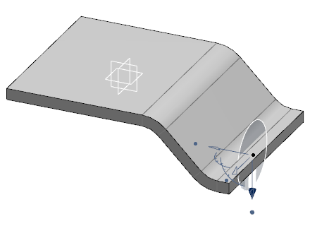
Notes:
- If several connections are possible when creating a wall from the extrusion of a given face, -select the faces you want to connect before clicking Wall .
- You can disconnect faces of a wall if a wire is on the top or bottom face of the wall. To do so, select a wire and in the context toolbar, click Disconnect using selected edge
 .
.