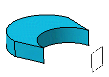
Creating Symmetries | |||
| |||
-
From the Transform section of the action bar, click
Symmetry
 if you are
working in Part Design or click Symmetry
 if you are
working in Sheet Metal Design.
Warning: In the Sheet Metal Design app, you can apply the command to solid sheet metal features only. The system issues a question about the result you wish to obtain:
- You can keep the new specifications induced by the operation by clicking Yes to go on using the command you have just selected.
OR
-
Click
Yes.
The Symmetry.x dialog box opens.

-
Select a point, line or plane as the reference element.
-
Click
OK to create the symmetrical element.
The original element is no longer visible but remains in the tree. A Symmetry.xxx feature is added to the tree.

Important: Contextual commands creating reference elements you need are available from the Reference box: - Insert Wireframe > Create Point: For more information, see Generative Shape Design User's Guide: Creating Wireframe Geometry: Creating Points.
- Insert Wireframe > Create Midpoint: Creates the midpoint of the line you select
- Insert Wireframe > Create Endpoint: Creates the endpoint of the line you select
- Insert Wireframe > Create Line: For more information, see Generative Shape Design User's Guide: Creating Wireframe Geometry: Creating Lines.
- Insert Wireframe > Create Plane: For more information, see Generative Shape Design User's Guide: Creating Wireframe Geometry: Creating Planes.
- Insert Wireframe > XY Plane: The XY plane of the current coordinate system origin (0,0,0) becomes the limiting element.
- Insert Wireframe > YZ Plane: The YZ plane of the current coordinate system origin (0,0,0) becomes the limiting element.
- Insert Wireframe > ZX Plane: The ZX plane of the current coordinate system origin (0,0,0) becomes the limiting element.
- Insert Wireframe > Create Intersection: For more information, see Generative Shape Design User's Guide: Creating Wireframe Geometry: Creating Intersections.
- Insert Wireframe > Create Projection: For more information, see Generative Shape Design User's Guide: Creating Wireframe Geometry: Creating Projections.
- Insert Operations > Create Boundary: For more information, see Generative Shape Design User's Guide: Performing Operations on Shape Geometry: Creating Boundaries.
- Insert Operations > Create Extract: For more information, see Generative Shape Design User's Guide: Performing Operations on Shape Geometry: Extracting Geometry: Extracting Elements.
- Insert Operations > Create Extract (in point): For more information, see Generative Shape Design User's Guide: Performing Operations on Shape Geometry: Extracting Geometry: Extracting Elements.
- Insert Operations > Create Extract (in tangency): For more information, see Generative Shape Design User's Guide: Performing Operations on Shape Geometry: Extracting Geometry: Extracting Elements.
- Insert Operations > Create Multiple Extract: For more information, see Generative Shape Design User's Guide: Performing Operations on Shape Geometry: Extracting Geometry: Extracting Sub-Elements.
- Insert Operations > Create tessellateCreates a Tessellate.