- Right-click the assembly in the tree and
select .
- Switch to the Sheet Metal Design app.
-
From the Model section of the action bar, click Sheet Metal
Parameters
 . .
The Sheet Metal Parameters Definition dialog box
appears.
- Define the parameters.
- Click OK.
- From , select the
Keep link with selected object option.
- Click OK.
- From the Model section of the action bar, click Positioned Sketch
 . .The Sketch Positioning dialog box appears. - Select the plane and click OK.
- From the Sketch section of the action bar, click Profile
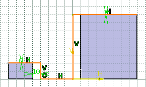
 . . - Sketch the profile and set the constraints as shown
below:
- Click Exit app
 to return to the 3D area. to return to the 3D area. - From the Model section of the action bar, click
Extrusion
 . . - Select the profile.
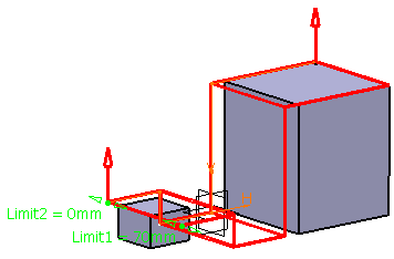
The Extrusion Definition dialog box appears. - Modify the dimension of the first limit.
- Click Preview.
- Click OK.
The extrusion is created and the tree is updated accordingly. 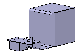
|