Creating Hoppers

You can create surfacic hoppers.

Hoppers are defined by a ruled surface or a double curvature surface and created using the loft command. Defining a surfacic hopper using a loft is highly recommended since it allows detection of all canonical segments.

This task shows you how to:


Before you begin: Sketch two profiles defined by an edge for surfacic hoppers or two points for canonic hoppers, and create with an opening line (for unfolding operations).

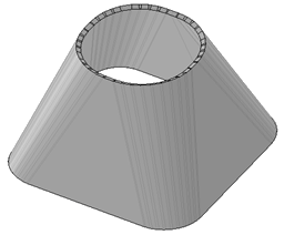
Create Surfacic Hoppers from a Ruled Surface

You can create surfacic hoppers from a ruled surface.

  1. From the Model section of the action bar, click Hopper .
  2. Right-click the Selection box and select Insert Surfaces > Create Multi-sections Surface.
  3. Select the two sketches in the tree as surfaces.


    : section 1

    : closing point 1

    : section 2

    : closing point 2

    Important: The two sketches that define the loft can be on parallel or non parallel planes.
  4. In the Coupling tab, couple sketches together by selecting points.


    : section 1

    : closing point 1

    : section 2

    : closing point 2

    : couplings

  5. To visualize the multi-sections surface, click Preview.

    A preview of the unfolded hopper is displayed, as well as its thickness in light blue.

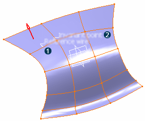
    A reference wire and invariant point are automatically selected. To modify them:

    1. Select a reference wire lying on the surface of the hopper.


    2. Select an invariant point that lies both on the surface and on the reference wire.


      Important: The reference wire and the invariant point, used to unfold the hopper, must lie on the surface, as well as the tear wire.
  6. Optional: Select the Neutral fiber check box if the selected input surface is not ruled.
  7. Select a tear wire.
    The unfolded view of the hopper starting from the tear wire appears.

    Important: A hopper can only be created if the surface shows a tangency continuity.
  8. To offset the surfacic hopper, enter a value in the Offset box.

    By default, there is no offset and the value is set to 0mm.

    The offset of the hopper is previewed.
  9. Click OK.
  10. Optional: From the standard area section of the action bar, click Fold/Unfold to unfold the hopper.

Create Surfacic Hoppers from a Double Curvature Surface

You can create surfacic hoppers from a double curvature surface.

  1. From the Model section of the action bar, click Hopper .
  2. Select a double curvature surface in the tree or in 3D area
    A Reference wire and an Invariant point are automatically detected.

    : reference wire

    : invariant point

    You can modify the Reference wire and the Invariant point :

    1. Click the Reference wire and Invariant point boxes.
    2. Select the reference wire and the invariant point directly in the work area.

  3. Click Preview to preview the unfolded hopper.


  4. Click Close to close the Flattened Surface Length Distortions dialog box and go back to the Hopper dialog box.
  5. To offset the surfacic hopper, type the desired value in the Offset box.

    By default, there is no offset and the value is set to 0mm.

    The offset is previewed.
  6. Click OK.
  7. From the standard area area of the action bar, click Fold/Unfold .
    The hopper is unfolded:

    Important: The symmetry might not be preserved.

Create Canonic Hoppers

You can create canonic hoppers.

  1. From the Model section of the action bar, click Hopper .
  2. Select Canonic Hopper.
  3. Select the sketches for the First profile and Second profile.
  4. To define the opening line, select the First point and Second point.
    Important: The first point must be on the first profile and the second point must be on the second profile.

    A preview of the hopper is displayed. You can notice two arrows starting from the first point.

    • The green arrow indicates the fixed side for unfolding: the hopper may be unfolded from the side opposite to the arrow. You can change the unfolding direction by clicking either the arrow or Invert fixed area side.
    • The red arrow indicates the direction for thickening the hopper. You can change the thickening direction by clicking either this red arrow or Reverse .
  5. Optional: To create a hopper between two profiles having different approximation parameters, click Generate lofted bend.

    The profiles can be open or closed, have sharp or smooth corners, or circular sections. Sharp corners are smoothed.

  6. Define the approximation parameters:


    : Number of segments

    : Chord tolerance

    : Segment length

    : Segment angle

    A square to round hopper would look like this:

  7. Click OK.
  8. From the standard area section of the action bar, click Fold/Unfold to unfold the hopper.