Extracting an Order Process in a Drawing View | |||
| |||
- In the Drafting app, from the View Layout section of the action bar, click Front View
 .
. -
Still in the Drafting
app, from the View Layout section of
the action bar, click Sheet metal Order Process
Table
 .
The Sheet metal Order Process Table Definition dialog box appears. It lets you manage how the drawing will be generated for all the order process views.
.
The Sheet metal Order Process Table Definition dialog box appears. It lets you manage how the drawing will be generated for all the order process views.
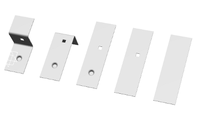
All technological data, relative to each bend, stamp, chamfer or cut are reported in a non editable table. It is automatically updated when the order process is modified and updated.
The order process front views are generated in the drawing sheet.
