Creating Standard Components

You can create standard parts and assembly components.

This task shows you how to:


Before you begin: Assign the Common Reference System resource in the Common Geometry Resource resource table in Data Setup.

Create a Standard Part Component

You can create a standard part component using the Generative Wireframe and Surface, Part Design Essentials, and Steel Outfitting Design apps.

  1. Create a 3D part.
    A node is added in the tree.
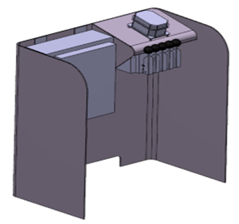
  2. Design the below shape using the commands available in the Generative Wireframe and Surface, and Part Design Essentials apps.


    For more information, see Generative Shape Design User's Guide and Part Design User's Guide.

  3. Activate the product level.
  4. Switch to the Steel Outfitting Design app.
  5. From the Component section of the action bar, click Standard Definition .
    The Set Up Wizard dialog box appears.
  6. In the Reference box, select a 3D part.
  7. Select an axis system as a reference to position the part component.
    1. Under Axis List, click Add an Axis System .
      The Axis System.1 is added in the Axis Name column.
    2. In the Host Type column, select Surface.
      Note: Click to remove the corresponding row containing axis system and host.
  8. Optional: Set other options.
    • Under Space Reservation, select the volume different than the geometry of the component.

      Note: This volume is reserved for the component and considered during the interference checking.

    • Under Snapping Planes, select the reference planes to align a component.
    • Under Public Parameters, select the required parameters declared by the administrator.
  9. Click .

Create a Standard Assembly Component

You can create a standard assembly component using the Assembly Design and Steel Outfitting Design apps.

  1. Create a product.
    The node is added in the tree.
  2. Design the below component using the commands available in the Assembly Design app.


    For more information, see Assembly Design User's Guide.

  3. Activate the root product.
  4. Switch to the Steel Outfitting Design app.
  5. Insert a representation.

    Note: The product must have a directly assigned representation to define as a component.

  6. From the Component section of the action bar, click Standard Definition .
    The Set Up Wizard dialog box appears.
  7. In the Reference box, select a product.
  8. Select an axis system as a reference to position the assembly component.
    1. In the Axis List area, click Add an Axis System .
      The Axis System.1 is added in the Axis Name column.
    2. In the Host Type column, select Surface.
  9. Optional: Set other options.
    • In the Volume box (Space Reservation area), select the volume different than the geometry of the component.
      Note: This volume is reserved for the component and considered during the interference checking.
    • In the Snapping Planes box, select the reference planes to align a component.
    • In the Public Parameters box, select the required parameters declared by the administrator.
  10. Click .