Creating a Steel Outfitting System for Functional usage | |||
| |||
- Create the
Functional Design node in the tree under the Steel Outfitting Design node:
- Right-click the Steel Outfitting Design node in the tree and select Insert > Extended Product.
- In the
New Content
dialog box, select Types > Steel Outfitting > Steel Outfitting System
 .
.
-
In the Steel Outfitting System dialog box,
specify the title of the root product (for example Functional Design) and the design range, and click OK.
Notes:
- Make sure that the Create 3D Part check box is selected in the 3D Part tab.
- The Steel Outfitting Design app supports normal and large ranges only.
- Double-click the 3D Shape node in the tree (available under the Functional Design node) to activate it.
-
Optional:
Change the visualization of the structural objects.
- From the Grid section of the action bar, click Visu Assistant
 .
. - In the Visu Assistant panel, expand the Dynamic Assistant area.
- In the dynamic object tree view area, hide or show the required group, product, and feature.
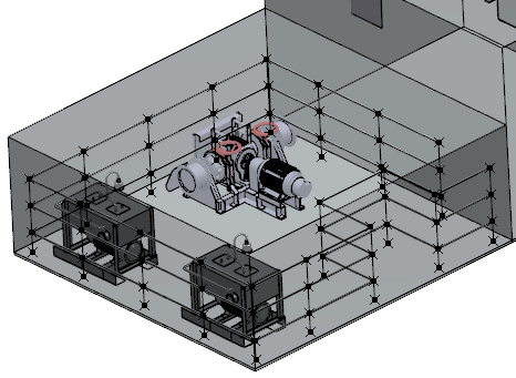
In this scenario, hide the Reserve Areas, Components, and Covering products for better visibility.
For more information, see Working with Visu Assistant. - From the Grid section of the action bar, click Visu Assistant
-
Create the base curves.
- From the Compass, click Part Design Essentials.
- Right-click the 3D Shape node in the tree and select Insert > 3D Shape.x > Geometrical Set to add a node (for example BaseCurves).
-
Draw the base curves in the form of 2D profiles.
For more information, see Part Design User's Guide: Creating a Positioned Sketch.
-
Create the points on the base curves to position a stanchion.
- From the Compass, click Steel Outfitting Design.
- Create a geometric set (for example StanchionPt) under the 3D Shape node by referring the step 4 (b).
- From the Geometric Operations section of the action bar, click Point
 .
. - Create the points on the base curves.
-
Create the stanchion lines.
- Create a geometric set (for example Rails) under the 3D Shape node by referring the step 4 (b).
- Create a line.
- Create a user feature of the line to reuse it.For more information, see 3D Templates Capture User's Guide: Creating and Working with User Features: Creating a User Feature.
- Instantiate the user feature.For more information, see 3D Templates Capture User's Guide: Creating and Working with User Features: Instantiating a User Feature.
-
Create the rail lines.
- Create a geometric set (for example Stanchion) under the 3D Shape node by referring the step 4 (b).
- Create a 2D profile of lines for the railing purpose.
- Create a power copy of the profile to reuse it.For more information, see 3D Templates Capture User's Guide: Creating and Instantiating Power Copies: Creating a Power Copy.
- Instantiate the power copy.For more information, see 3D Templates Capture User's Guide: Creating and Instantiating Power Copies: Instantiating a Power Copy.
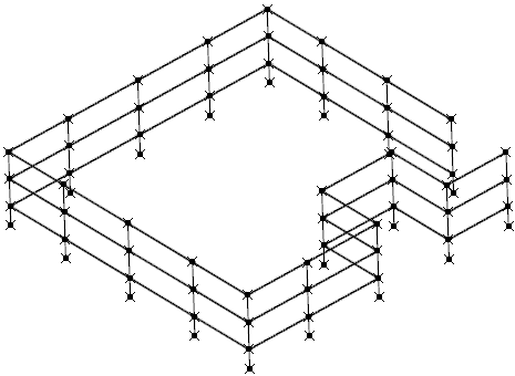
The profile of the handrail is created.
- Click Visu Assistant
 to show the Reserve Areas, Components, and Covering products.