-
Activate a 3D shape representation.
-
From the Operations section of the
action bar, click
Cutting Element
 . .
The Cutting Element dialog box
appears.
-
In the Category box, select the required category.
Note:
These options are available depending on the dictionary set in Data Setup.
-
Under
Support, select the required deck planes.
Notes:
- The selected planes should be parallel to each other.
- You can also select a surface as a support for cutting
element.
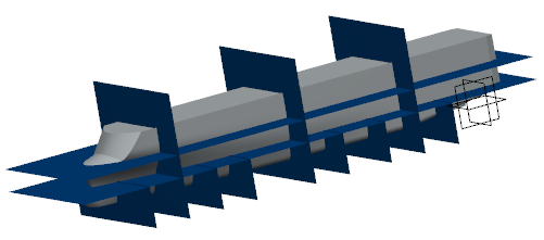
The horizontal cutting elements are created with deck supports. Note:
You can:
- Click Reference Plane Browser
 . . The Plane Systems dialog box appears.
You can select reference planes directly from
Selection List or create formulas for
the selection of planes under Formula.
For more information, see About Using Reference Planes Browser.
Note:
To use Reference Plane Browser, a
space reference system must be set in the Common
Geometry Resource table in Data Setup.
- Select the required cutting element under
Support and do the following:
- Click Delete
 or Replace or Replace
 to remove or replace the selected support respectively. to remove or replace the selected support respectively.
- Enter a value in the box available next to the selected
support to change its offset. The offset can be applied to
only planar supports.
- Right-click the required cutting element under
Support and do the following:
- Select Center Graph to view the
selected element in the center of the work area.
- Select Reframe On to improve the
visibility of the selected element.
- Select Hide/Show to hide and show the
selected element.
-
Optional: Under Limits, select the limits:
- One dimensional features such as sketch, edges, lines, splines, etc.
- Two dimensional features such as wire, surface, plane, cutting element,
etc.
- Volumes
Note:
You can:
- Click
 to create a sketch limit. The sketch is
positioned on the first support selected under
Support. to create a sketch limit. The sketch is
positioned on the first support selected under
Support.
- Select the limiting element under Limits and do the following:
- Click Delete
or Replace
to remove or replace the limiting element respectively.
- Click Flip to consider the other side
of the selected deck planes cut by the limiting element.
-
Optional: Clear the Automatic check box and
enter the required name in the Name box.
-
Click
OK.
The horizontal cutting elements are created under a geometrical set. If the
Enable hybrid design inside part bodies and bodies
check box available at is selected, the cutting elements are created under a hybrid body
or a geometrical set depending on the option specified.
-
Create other cutting elements supported on cross/long planes (as per your
requirements) by repeating the above steps.
|
 > Preferences is selected, the cutting elements are created under a hybrid body
or a geometrical set depending on the option specified.
> Preferences is selected, the cutting elements are created under a hybrid body
or a geometrical set depending on the option specified.