While you are creating or editing a 3D curve, you can right-click a control point to access a context menu which will give you a range of options to help you define the control point.
Depending on your selection in the Creation type area of the 3D curve dialog box when the curve was created, the context menu contains the following options:
Edit
When you select Edit from the context menu, the Tuner dialog box is displayed. This allows you to
redefine the tangency position (X, Y, and Z axes), and its vector's
step.
The Relative check box enables you to redefine the
tangency relative position (X, Y, and Z axes), and its vector's
step.
The Reset Origin button allows you to reset the origin
of the relative position.
Keep this point
When you select Keep this point from the context menu, you create a point at this location.
A datum Point.xxx appears in the tree.
Impose Tangency
When a curve is created in Through points or Near
points mode, and its first point is constrained on any point
of another curve, the new curve automatically is tangent to the
curve on which its first point is constrained. As soon as the
curve's second point is created, the imposed tangent is displayed
on the new curve.
To deactivate the default option, unselect the Impose
Tangency context menu on the tangent vector.
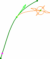
When creating a 3D curve, you may want to impose tangency
constraints on specific points of the curve. Then if you move the
point at which a tangency constraint has been set, the curve will
be recomputed to retain this tangency constraint at the point's new
location.
Depending on the creation mode, you can impose this constraints on
a limited number of points:
- In Through points mode tangency can be imposed on any
point
- In Near points mode tangency can be imposed
independently on each end points only
- In Control points mode no tangency constraint can be
imposed (end points can be constrained on other elements). See also
Constrain this point.
Impose Curvature
When you select Impose Curvature from the context menu, you impose the curvature constraint on the selected point or points. An arrow representing the curvature direction (vector) is
displayed. Modifying the vector direction modifies the curvature
direction.
The direction of the curvature is constrained in the plane defined
as normal to the tangent vector.
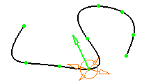
- To impose a curvature continuity, you must ensure that a tangency
continuity already exists.
- This option is only available for the Through points and
Near Points
creation type.
Set as Arc Limit
When you select Set as Arc Limit from the context menu, you can start/stop an arc at this point. The curve will pass through this point.
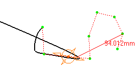
This option is only available for the Near points creation type.
- Press F5 to move the handles into a different plane of the Robot.
- Use the standard shortcuts (Ctrl and Shift keys) to select,
multi-select, and unselect any combination of control points on
these curves.
- You cannot add a point past the end points. To do this, you need to add a point before the end point, move the new point where the end point lies, then move the end point to a new location.
- The creation plane for each free point is defined according to the current plane/Robot orientation on the previous point. Therefore you can change creation planes within the same curve, by setting a new current plane/Robot orientation on several points.
Remove this point
Removes the point from the 3D area and the tree.
Constrain this point
Even though you cannot impose a tangency constraint on a curve
created in Control points mode, you can constrain its
end points on another curve.
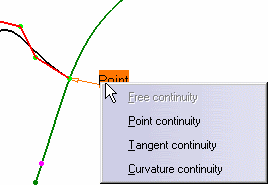
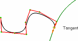
When setting a constraint on an end point, a text is displayed
indicating the type of continuity between the two curves.
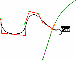
On right-clicking the text to display the context menu from which you can choose another continuity type: tangency, or curvature.
Notes:
- Press F5 to move the handles into a different plane of the Robot.
- Use the standard shortcuts (Ctrl and Shift keys) to select,
multi-select, and unselect any combination of control points on
these curves
.
- You cannot add a point past the end points. To do this, you need to
add a point before the end point, move the new point where the end
point lies, then move the end point to a new location.
- The creation plane for each free point is defined according to the current plane/Robot orientation on the previous point. Therefore you can change creation planes within the same curve, by setting a new current plane/Robot orientation on several points.


